Maintenance
2138−1/A1
Winterthur Gas & Diesel Ltd.
3/ 5
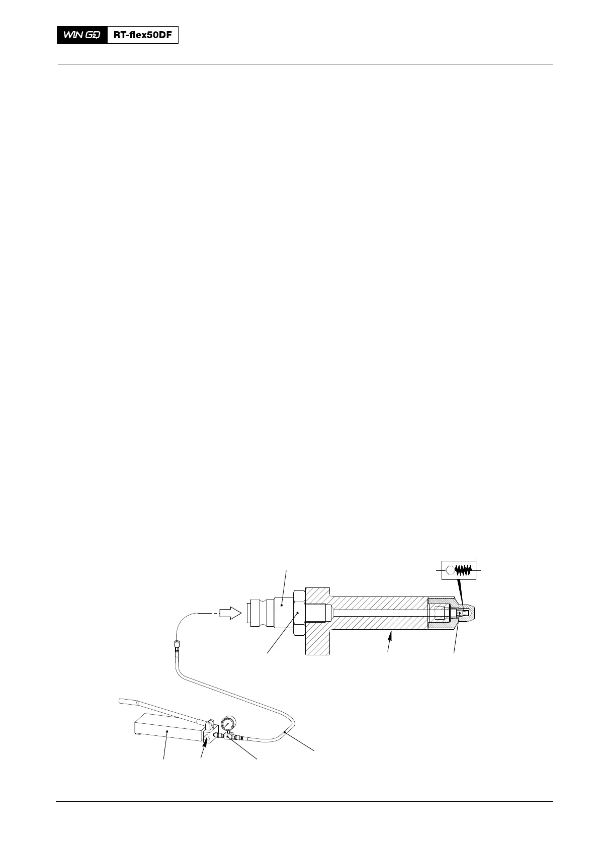
4. Lubricating Quill − Function Check
4.1 General
You do a function check to make sure that the non-return valve (3, Fig. 3) operates
correctly. The pressure that opens the non‐return valve is 5.0 bar.
During the function check, keep the lubricating quill (2) in a horizontal position.
For the function check, use an oil with a viscosity as given in the specifications that
follow:
D SAE 50 at 40_C (approximately 200 cSt)
D SAE 30 at 25_C (approximately 190 cSt).
4.2 Procedure
1) If necessary, remove the screw-in union (1) of the lubricating quill.
2) Install the nipple (94934I) to the lubricating quill (2).
3) Attach the HP hose to the nipple (94934I) and to the hydraulic distributor and
pressure gauge (94934H).
4) Install the the hydraulic distributor and pressure gauge (94934H) to the HP oil
pump (94931).
5) Hold the lubricating quill (2) up and operate the pump (94931) until oil that flows
has no air.
6) Open the relief valve (4) and decrease the pressure to 2.0 bar.
7) Close the relief valve (4).
8) Hold the lubricating quill (2) in a horizontal position.
9) Operate the HP oil pump (94931) to increase the pressure in steps of 1.0 bar
until the non-return valve (3) opens.
10) Record the opening pressure shown on the pressure gauge.
Note: The minimum permitted opening pressure is 4.25 bar. If necessary,
replace the defective lubricating quill (2).
94935
94931
94934H
4
Fig. 3
94934I
2
3
1
WCH03490
2016
Lubricating Quill