Maintenance2138−1/A1
Winterthur Gas & Diesel Ltd.
4/ 5
5. Installation
CAUTION
Damage Hazard: The surfaces of the cylinder liner and the nozzle
tip make a metallic seal. The seat angles in the cylinder liner and
on the nozzle tip are different. Do not use a gasket between the
cylinder liner and the nozzle tip, or damage to the equipment can
occur.
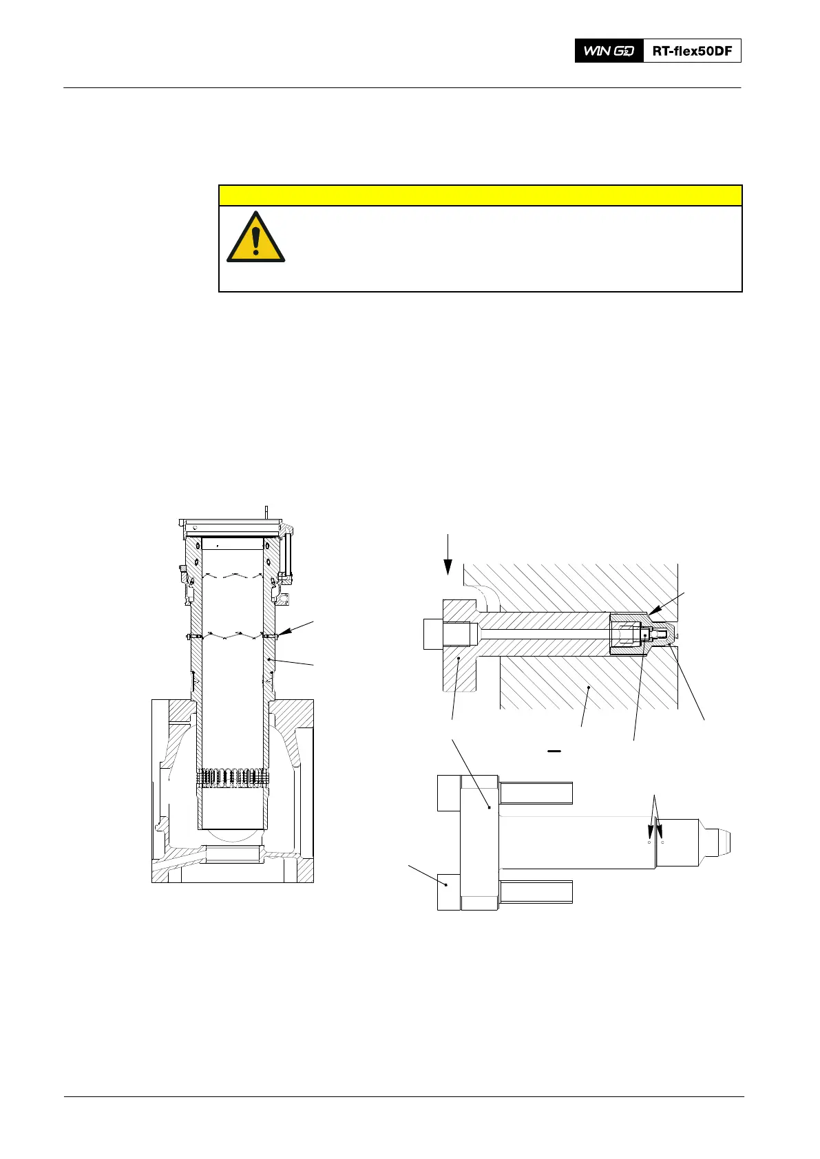
Note: When you install the lubricating quill , replace all components, i.e. nozzle
tip, non-return valve and holder (see Fig. 4).
1) Make sure that the sealing surfaces (3) are clean and have no damage.
2) Make sure that the marks (MK) are in line. If the marks are not in line, send the
lubricating quill to Wärtsilä.
3) Apply oil to the threads and surfaces of the screws (4).
4) Put the lubricating quill (1) in position.
5) Torque the two screws (4) to 10 Nm.
WCH03489
Fig. 4
2
1
I
I
MK
Holder
4
Nozzle
Tip
3
Non-return
Valve
WCH03490
2
2016
Lubricating Quill