Maintenance3326−2/A2
Winterthur Gas & Diesel Ltd.
8/ 10
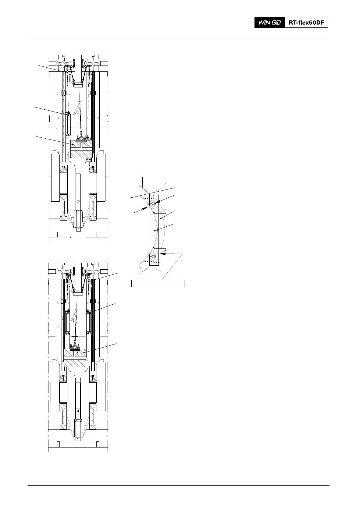
7) Turn the crosshead pin (1, Fig. 12) 90° .
8) Move the crosshead pin (1) to the
driving end.
9) Lower and align the guide shoe (2) with
the crosshead pin (1).
10) Move the crosshead pin (1) fully
through the guide shoe (2).
11) Lower and align the guide shoe (3) with
the crosshead pin (1).
12) Align the crosshead pin (1) with the two
guide shoes (2, 3).
13) Attach the two holding plates (5) to the
to the guide shoe (2, 3) with new tab
washers (6) and bolts (4).
14) Make sure that there is no clearance
between the holding plates (5) and the
crosshead pin (1).
15)
Crosshead Pin − Removal and Installation
2016
Fig. 12
DRIVING END
H4
013.243/05
H5
3
1
FREE END
013.244/05
2
1
1
4
2, 3
6
WCH03529
NO CLEARANCE
5