Maintenance
3326−2/A2
Winterthur Gas & Diesel Ltd.
7/ 10
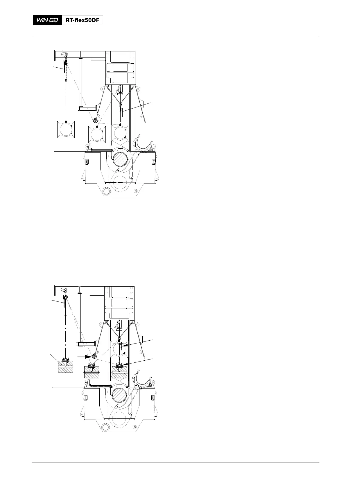
6) Attach the chain block (H6, Fig. 10) to
the guide shoe.
7) Operate the manual ratchet (H1) and
the chain block (H6) to remove the
guide shoe from the engine.
8) Do step 2) to step 6) for the guide shoe
attached to the manual ratchet (H5).
4. Guide Shoes −
Installation
Note: When you the steps below, make
sure that you install the guide
shoes in their original positions.
1) Attach the chain block (H6) and the
manual ratchet (H1) to the guide shoe.
2) Apply a light tension to the chains of
the manual ratchets (H6, H1)
Note: When you step 3) to step 5), keep
the tension on the two manual
ratchets.
3) Operate the chain block (H6) and the
manual ratchet (H1) to move the guide
shoe through the door frame.
4) Attach the manual ratchet (H5, Fig. 9)
to the eye bolt on the guide shoe. Apply
tension to the chain.
5) Remove carefully the chain block (H6).
6) Operate the manual ratchets (H5, H1)
to lift the guide shoe.
7) Remove the manual ratchet (H1).
8) Do step 1) to step 7) for the other guide
shoe (use the manual ratchet (H4) .
5. Crosshead Pin −
Installation
1) Clean the crosshead pin (1, Fig. 11)
and the guide and bearing surfaces.
2) Make sure that the surfaces of the
crosshead pin are clean and have no
damage.
3) Apply bearing oil to the crosshead
pin (1) and all guide and bearing
surfaces.
4) Attach the chain block (H6) and the
manual ratchet (H1) to the crosshead
pin (1).
5) Operate the chain block (H6) and the
manual ratchet (H1) to move the
crosshead pin (1) through the door
frame.
6) When the crosshead pin is in the
column, remove the chain block (H6).
Crosshead Pin − Removal and Installation
2016
013.249/05a
H1
H6
Fig. 10
013.245/05a
94324
I
H6
H1
Fig. 11
1