Maintenance3326−2/A2
Winterthur Gas & Diesel Ltd.
6/ 10
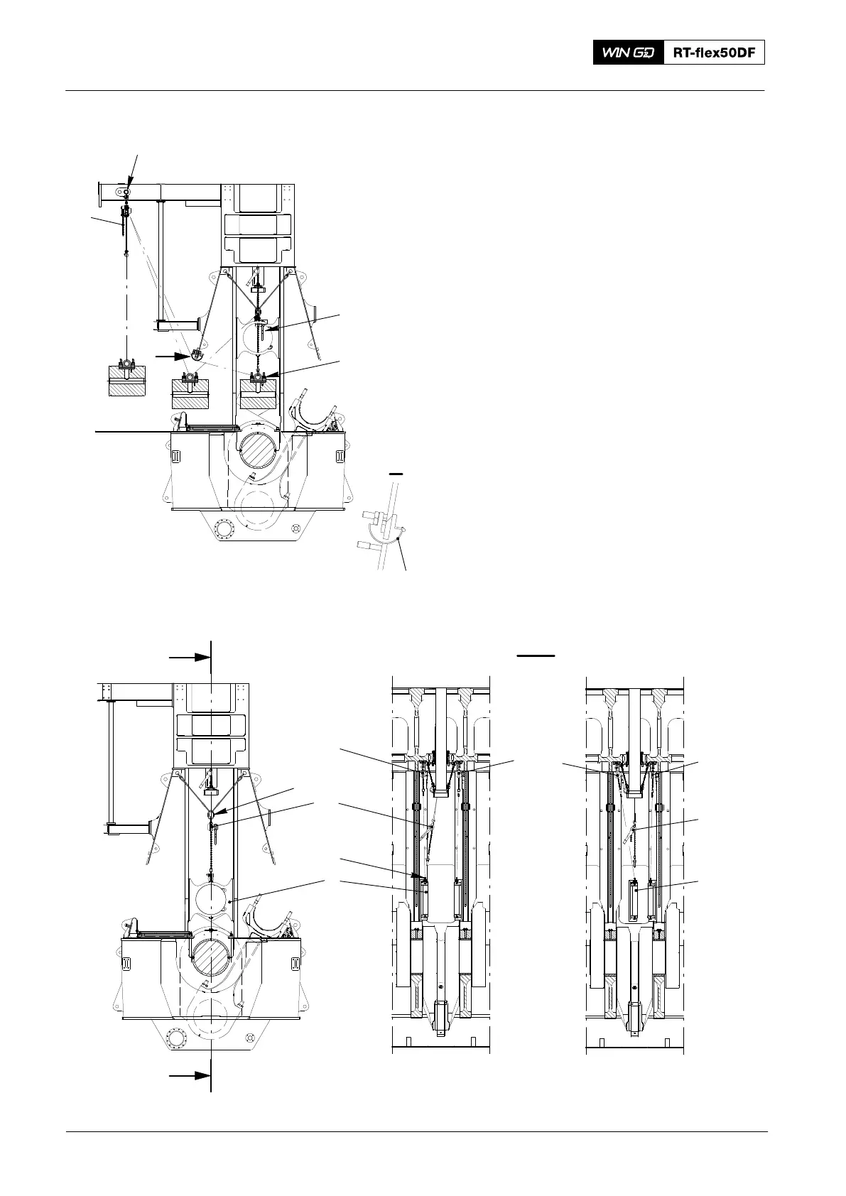
23) Attach the lifting tool (94335, Fig. 8)
between the double-I girders.
24) Attach the chain block (H6) to the lifting
tool (94335).
25) Turn the crosshead pin 90_.
26) Attach the chain block (H6) to the
crosshead pin.
27) Operate the manual ratchet (H1) and
the chain block (H6) to remove the
crosshead pin from the column.
3. Guide Shoes − Removal
1) Record the positions of the guide
shoes. The shims of the guide shoes
can have different dimensions. This will
help you during the installation
procedure.
2) Attach the manual ratchet (H1, Fig. 9)
to the eye bolt (EB) at the free end.
3) Lower the guide shoe to the door
frame.
4) Remove the manual ratchet (H4).
5) Turn the guide shoe (1) in the center of
the cylinder.
H5
H4
H5
H4
H1
H1
94666
EB
1
I
I
I - I
013.246/05
013.247/05
013.248/05
1
DRIVING END
Fig. 9
Crosshead Pin − Removal and Installation
2016
013.245/05a
94324
94335
94117A
I
I
Fig. 8
H6
H1