03/2003
6-30
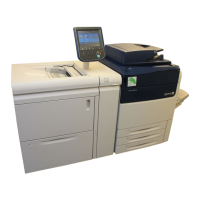
8850/ 510DP
Installation Procedure
General Procedures
23. (Figure 17): Prepare to level the Printer. Rotate the leveling bolts (located inside the front
and rear doors) fully counterclockwise.
Figure 17 Preparing to level the Printer
24. (Figure 18): Check the front-to-rear level of the Printer.
Figure 18 Checking the level of Printer
NOTE: To ensure that the Printer frame is not twisted, use a level on both end frames to per-
form the side-to-side level check.
NOTE: Adjust the end that is farthest out of level first.
Rotate bolts fully counterclockwise
1
Place the level
on the metal
edge of the
developer
module and
check the
front-to-rear
level of the
Printer.
3
Repeat the side-to-side
level check at the other
end of the Printer.
2
Check the side-to-side level
at the base of the Printer.
 Loading...