03/2003
6-37
8850/ 510DP
Removal Procedure
General Procedures
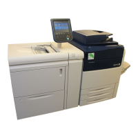
16. (Figure 2): Raise the image module and engage the developer module shipping brackets.
Figure 2 Engaging the Shipping Brackets
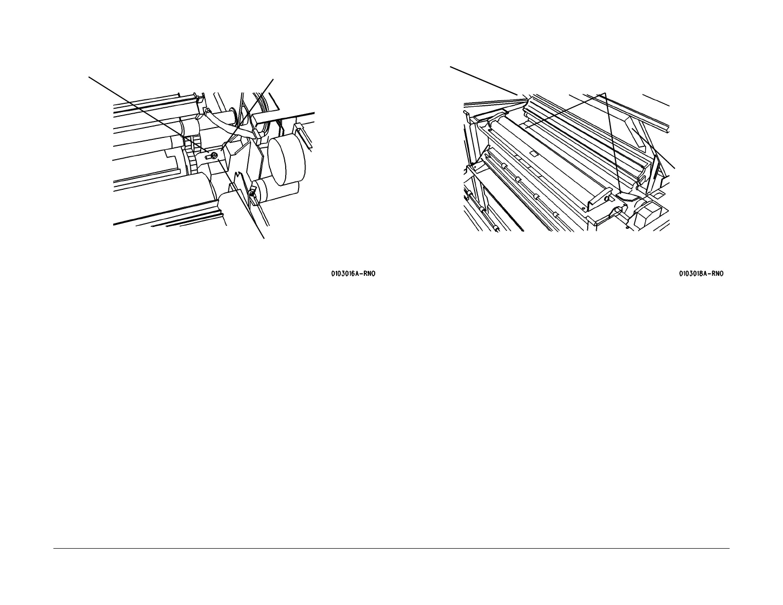
17. (Figure 3): Install the shipping pads.
Figure 3 Installing the Shipping Pads
18. Remove the Charge Scorotron Assembly (REP 9.8), wrap the assembly in bubble pack,
and place it in a Roll Media Supply Drawer.
19. Remove the Heat Rods (REP 10.1).
a. Wrap in bubble pack.
b. Tape cardboard to the entire length.
c. Place in a Roll Media Supply Drawer.
d. Secure the Roll Media Supply Drawer with tape
1
Loosen screw
2
Slide bracket onto the shaft
3
Retighten screw
4
Repeat steps 1 through 3
on other side
Image Module at Service Position
1
Install the shipping pads, one on
each end of the photoreceptor
2
Install the
foam pads,
one on each
side of the
top cover
 Loading...