16 www.xilinx.com Virtex-4 FPGA Configuration User Guide
UG071 (v1.12) June 2, 2017
Chapter 1: Configuration Overview
For power-up, the V
CCINT
power pins must be supplied with a 1.2V source. None of the
I/O voltage supplies (V
CCO
), except V
CCO_0
(V
CC_CONFIG
), need to be powered for
Virtex-4 configuration in JTAG or serial modes. Table 1-3 shows the power supplies
required for configuration; for recommended operating conditions, see Table 2 of the
Virtex-4 FPGA Data Sheet. Table 41 of the Virtex-4 FPGA Data Sheet shows the configuration
power-up timing parameters. Table 7-1 shows the number of frames per Virtex-4 device.
V
CCINT
should rise monotonically within the specified ramp rate. If this is not possible,
delay configuration by holding the INIT_B pin or the PROGRAM_B pin Low (see
“Delaying Configuration”) while the system power reaches V
POR
.
The configuration logic power input (V
CC_CONFIG
) and the auxiliary voltage input
(V
CCAUX
) are used as a logic input to the Power-On-Reset (POR) circuitry. If either of these
voltage planes dips below the specified level, POR can trigger.
Clear Configuration Memory (Step 2, Initialization)
Table 1-3: Power Supplies Required for Configuration
Pin Name Description
V
CCINT
Internal core voltage relative to GND.
V
BATT
(1)
Encryption Key battery supply.
V
CC_CONFIG
Configuration output supply voltage (also known as V
CCO_0
)
V
CCAUX
Auxiliary power input for configuration logic and other FPGA functions.
Notes:
1. V
BATT
is required only when using bitstream encryption.
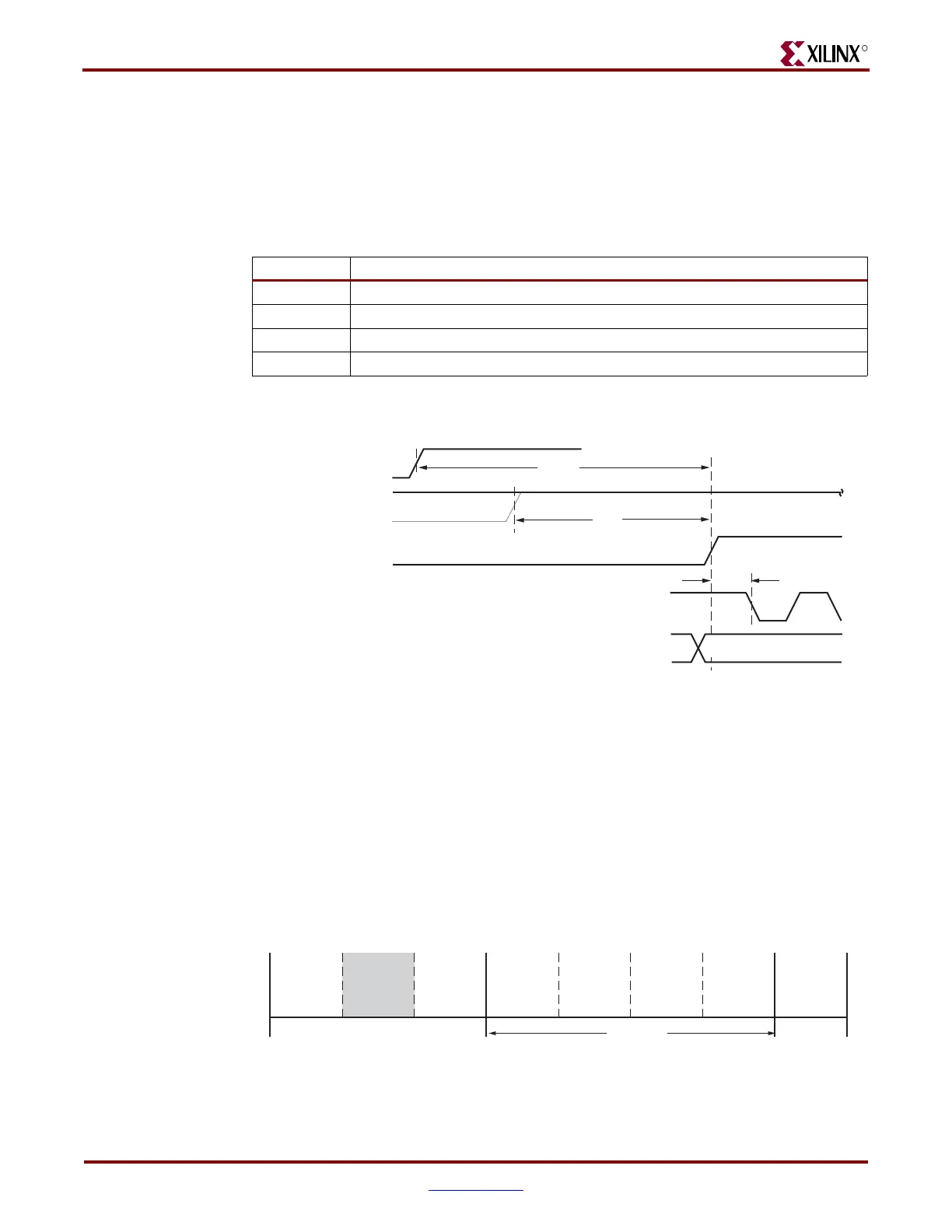
Figure 1-3: Device Power-Up Timing
T
ug071_03_073007
V
CC
T
POR
T
PL
T
ICCK
PROGRAM_B
INIT_B
CCLK Output or Input
VALID
M0, M1, M2*
(Required)
*Can be either 0 or 1, but must not toggle during and after configuration.
Figure 1-4: Initialization (Step 2)
Device
Power-Up
Sample Mode
Pins
Synchronization
Device ID
Check
CRC Check
Clear
Configuration
Memory
Startup
Sequence
Load
Configuration
Data
Start
Finish
ug071_04_122105
Bitstream
Loading
Steps
12345678

 Loading...


