Virtex-4 FPGA Configuration User Guide www.xilinx.com 33
UG071 (v1.12) June 2, 2017
Serial Configuration Interface
Mixed Serial Daisy Chains
Virtex-4 devices can be daisy-chained with the Virtex, Spartan®-II, Virtex-E, Spartan-IIE,
Virtex-II, Virtex-II Pro, and Spartan-3 families. There are three important design
considerations when designing a mixed serial daisy chain:
• Many older devices cannot accept as fast a CCLK frequency as a Virtex-4 device can
generate. Select a configuration CCLK speed supported by all devices in the chain.
• Newer devices should be grouped at the beginning of the serial daisy chain, with
older devices located at the end of the chain.
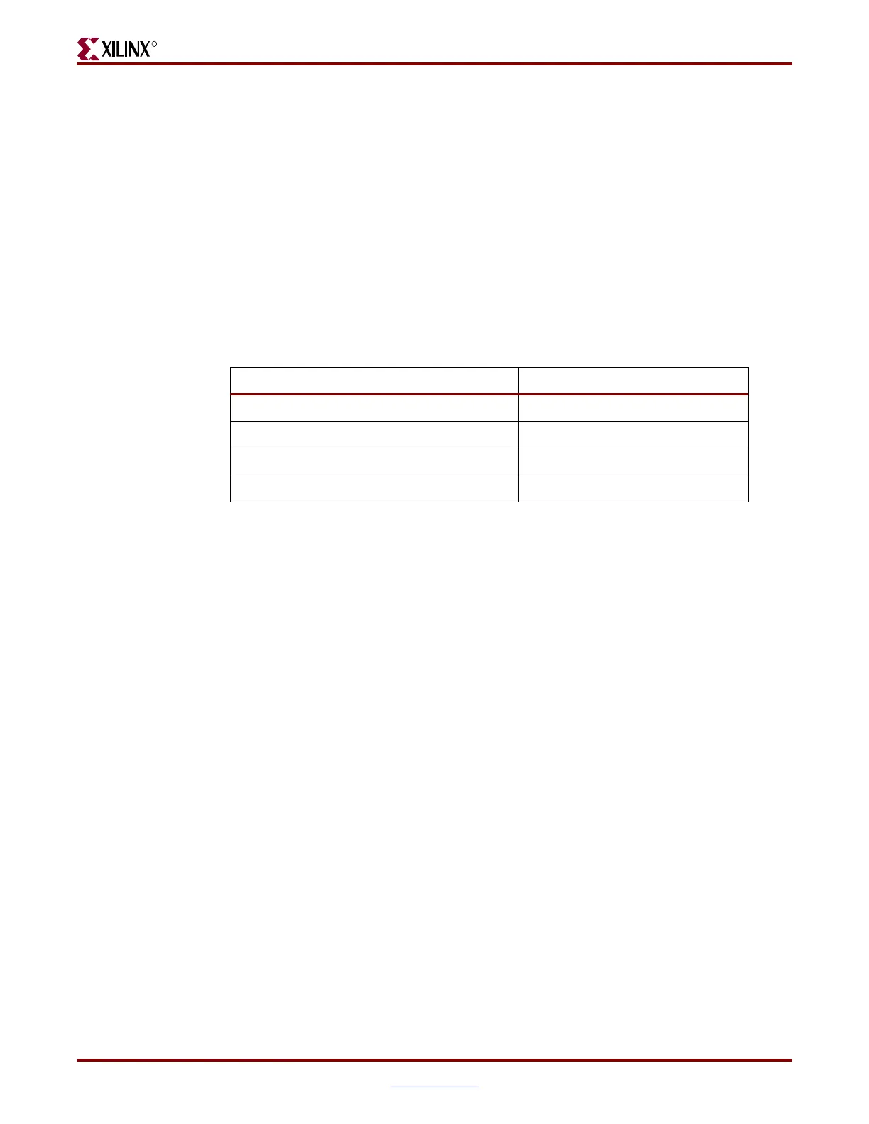
• The number of configuration bits that a device can pass through its DOUT pin is
limited. This limit varies for different families (Table 2-3). The sum of the bitstream
lengths for all downstream devices must not exceed the number in this table for each
family.
Guidelines and Design Considerations for Serial Daisy Chains
There are a number of important considerations for serial daisy chains:
Startup Sequencing (GTS)
GTS should be released before DONE or during the same cycle as DONE to ensure the
Virtex-4 device is operational when all DONE pins have been released.
Active DONE Driver
All devices except the first should disable the driver on the DONE pin (refer to the BitGen
section of the Development System Reference Guide for software settings):
• DriveDone enabled (first device)
• DriveDone disabled (all devices except the first)
Alternatively, the driver can be disabled for all DONE pins and an external pull-up resistor
added to pull the signal High after all devices have released it.
Connect All DONE Pins
It is important to connect the DONE pins for all devices in a serial daisy chain. Failing to
connect the DONE pins can cause configuration to fail. For debugging purposes, it is often
helpful to have a way of disconnecting individual DONE pins from the common DONE
signal, so that devices can be individually configured through the serial or JTAG interface.
DONE Pin Rise Time
After all DONE pins are released, the DONE pin should rise from logic 0 to logic 1 in one
CCLK cycle. If there are several devices in the serial daisy chain or other loads on the
DONE signal (such as LEDs or microprocessor inputs), external pull-up resistors can be
Table 2-3: Maximum Number of Configuration Bits, Various Device Families
Architecture Maximum DOUT Bits
Virtex-4 32 x( 2
27
– 1) = 4,294,967,264
Virtex-II Pro, Virtex-II 32 x( 2
27
– 1) = 4,294,967,264
Spartan-3 32 x (2
27
– 1) = 4,294,967,264
Virtex, Virtex-E, Spartan-II, Spartan-IIE 32 x (2
20
– 1) = 33,554,216

 Loading...


