70 www.xilinx.com Virtex-4 FPGA Configuration User Guide
UG071 (v1.12) June 2, 2017
Chapter 3: Boundary-Scan and JTAG Configuration
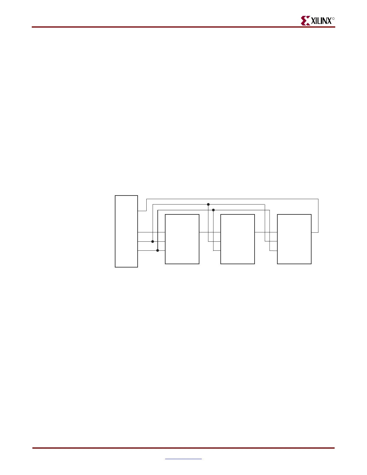
Multiple Device Configuration
It is possible to configure multiple Virtex-4 devices in a chain. (See Figure 3-7.) The devices
in the JTAG chain are configured one at a time. The multiple device configuration steps can
be applied to any size chain.
Refer to the state diagram in Figure 3-2 for the following TAP controller steps:
1. On power-up, place a logic 1 on the TMS and clock the TCK five times. This ensures
starting in the TLR (Test-Logic-Reset) state.
2. Load the CFG_IN instruction into the target device (and BYPASS in all other devices).
Go through the RTI state (RUN-TEST/IDLE).
3. Load in the configuration bitstream per step 7 through step 11 in Table 3-6.
4. Repeat step 2 and step 3 for each device.
5. Reset all TAPs by clocking five 1s on TMS.
6. Load the JSTART command into all devices.
7. Go to the RTI state and clock TCK 12 times.
All devices are active at this point.
Reconfiguring through Boundary-Scan
The ability of Virtex-4 devices to perform partial reconfiguration is the reason that the
configuration memory is not cleared when reconfiguring the device. When reconfiguring a
chain of devices, refer to step 3 in Table 3-6. There are two methods to reconfigure Virtex-4
devices without possible internal contention. The first method is to pulse the
PROGRAM_B pin, resetting the internal configuration memory. The alternate method is to
perform a shutdown sequence, placing the device in a safe state. The following shutdown
sequence includes using internal registers. (For details on internal registers, refer to
Chapter 8)
1. Load the CFG_IN instruction.
2. In the SHIFT-DR state, load the synchronization word followed by the Reset CRC
Register (RCRC) command.
1111 1111 1111 1111 1111 1111 1111 1111→ Dummy word
1010 1010 1001 1001 0101 0101 0110 0110→ Synchronization word
0011 0000 0000 0000 1000 0000 0000 0001→ Header: Write to CMD register
0000 0000 0000 0000 0000 0000 0000 0111→ RCRC command
0000 0000 0000 0000 0000 0000 0000 0000→ flush pipe
Figure 3-7: Boundary-Scan Chain of Devices
JTAG Header
ug071_36_073007
Virtex-4
FPGA
TDOTDI
TMS
TCK
Virtex-4
FPGA
PROGRAM_B
TDI
TMS
TCK
PROGRAM_B
TDO
Virtex-4
FPGA
TDI
TMS
TCK
PROGRAM_B
TDO
Device 0 Device 1 Device 2
TDO
TMS
TDI
TCK

 Loading...


