Virtex-4 FPGA Configuration User Guide www.xilinx.com 89
UG071 (v1.12) June 2, 2017
Configuration Control Logic
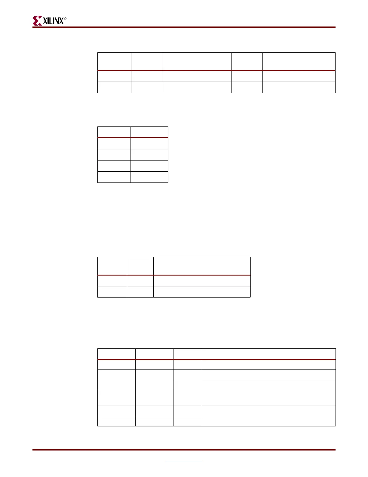
Type 2 Packet
The Type 2 packet, which must follow a Type 1 packet, is used to write long blocks. No
address is presented here because it uses the previous Type 1 packet address. The header
section is always a 32-bit word.
Following the Type 2 packet header is the Type 2 Data section, which contains the number
of 32-bit words specified by the word count portion of the header. See Table 7-4.
Configuration Registers
All bitstream commands are executed by reading or writing to the configuration registers.
Table 7-5 summarizes these registers. A detailed explanation of selected registers follows.
Table 7-2: Type 1 Packet Header Format
Header
Type
Opcode Register Address Reserved Word Count
[31:29] [28:27] [26:13] [12:11] [10:0]
001 xx RRRRRRRRRxxxxx RR xxxxxxxxxxx
Notes:
1. "R" means the bit is not used and reserved for future use.
Table 7-3: Opcode Format
Opcode Function
00
NOP
01 Read
10 Write
11 Reserved
Table 7-4: Type 2 Packet Header
Header
Type
Opcode Word Count
[31:29] [28:27] [26:0]
010 RR xxxxxxxxxxxxxxxxxxxxxxxxxx
Table 7-5: Configuration Registers
Reg. Name Read/Write Address Description
CRC
Read/Write 00000
CRC register
FAR
Read/Write 00001
Frame Address Register
FDRI
Write 00010
Frame Data Register, Input (write configuration data)
FDRO
Read 00011
Frame Data Register, Output register (read
configuration data)
CMD
Read/Write 00100
Command Register
CTL
Read/Write 00101
Control Register

 Loading...


