18 www.xilinx.com Virtex-4 FPGA Configuration User Guide
UG071 (v1.12) June 2, 2017
Chapter 1: Configuration Overview
Bitstream Loading (Steps 4-7)
The bitstream loading process is similar for all configuration modes; the primary
difference between modes is the interface to the configuration logic. Details on the different
configuration interfaces are provided in Chapter 2.
The most important steps in the bitstream loading process are, synchronization, device ID
check, loading configuration data, and the CRC check. Each of these steps involves distinct
parts of the configuration bitstream. The steps prior to synchronization and after the CRC
check do not directly involve the configuration bitstream.
Synchronization (Step 4)
Before the configuration data frames can be loaded, a special 32-bit synchronization word
(0xAA995566) must be sent to the configuration logic. The synchronization word alerts
Table 1-4: Signals Relating to Initialization and Delaying Configuration
Signal Name Type
(1)
Access
(2)
Description
PROGRAM_B Input Externally accessible via
the PROGRAM_B pin.
Global asynchronous chip reset.
Can be held Low to delay
configuration.
INIT_B Input or
Output
Externally accessible via
the INIT_B pin.
Before the MODE pins are
sampled, INIT_B is an input that
can be held Low to delay
configuration.
After the MODE pins are sampled,
INIT_B is an open-drain active
Low output indicating whether a
CRC error occurred during
configuration:
0 = CRC error
1 = No CRC error
INIT_COMPLETE Status Internal signal,
accessible through the
Virtex-4 status register.
Indicates whether INIT_B signal
has been internally released.
MODE_STATUS[2:0] Status Internal signals,
accessible through the
Virtex-4 status register.
Reflects the values sampled on the
MODE pins when INIT_B is
asserted High.
Notes:
1.
The Status type symbolizes an internal status signal without a corresponding pin.
2. Information on the Virtex-4 status register is available in Table 7-9. Information on accessing the
JTAG capture sequence is available in Table 8-4.
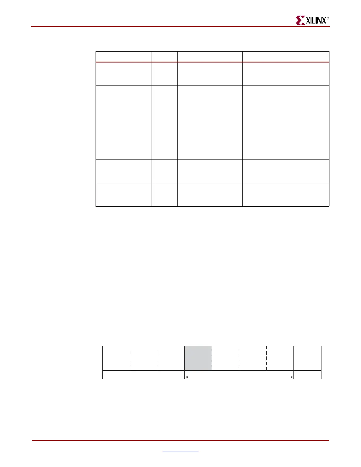
Figure 1-6: Synchronization (Step 4)
Device
Power-Up
Sample Mode
Pins
Synchronization
Device ID
Check
CRC Check
Clear
Configuration
Memory
Startup
Sequence
Load
Configuration
Data
Start
Finish
ug071_06_122105
Bitstream
Loading
Steps
12345678

 Loading...


