96 www.xilinx.com Virtex-4 FPGA Configuration User Guide
UG071 (v1.12) June 2, 2017
Chapter 7: Configuration Details
Bitstream Composition
Configuration can begin after the device is powered and initialization has finished, as
indicated by the INIT pin being released. After initialization, the packet processor ignores
all data presented on the configuration interface until it receives the synchronization word.
After synchronization, the packet processor waits for a valid packet header to begin the
configuration process.
Default Initial Configuration Process
Initial configuration using a default bitstream (a bitstream generated using the default
BitGen settings) begins by pulsing the PROGRAM_B pin for SelectMAP and Serial
configuration modes or by issuing the JPROG_B instruction for JTAG configuration mode.
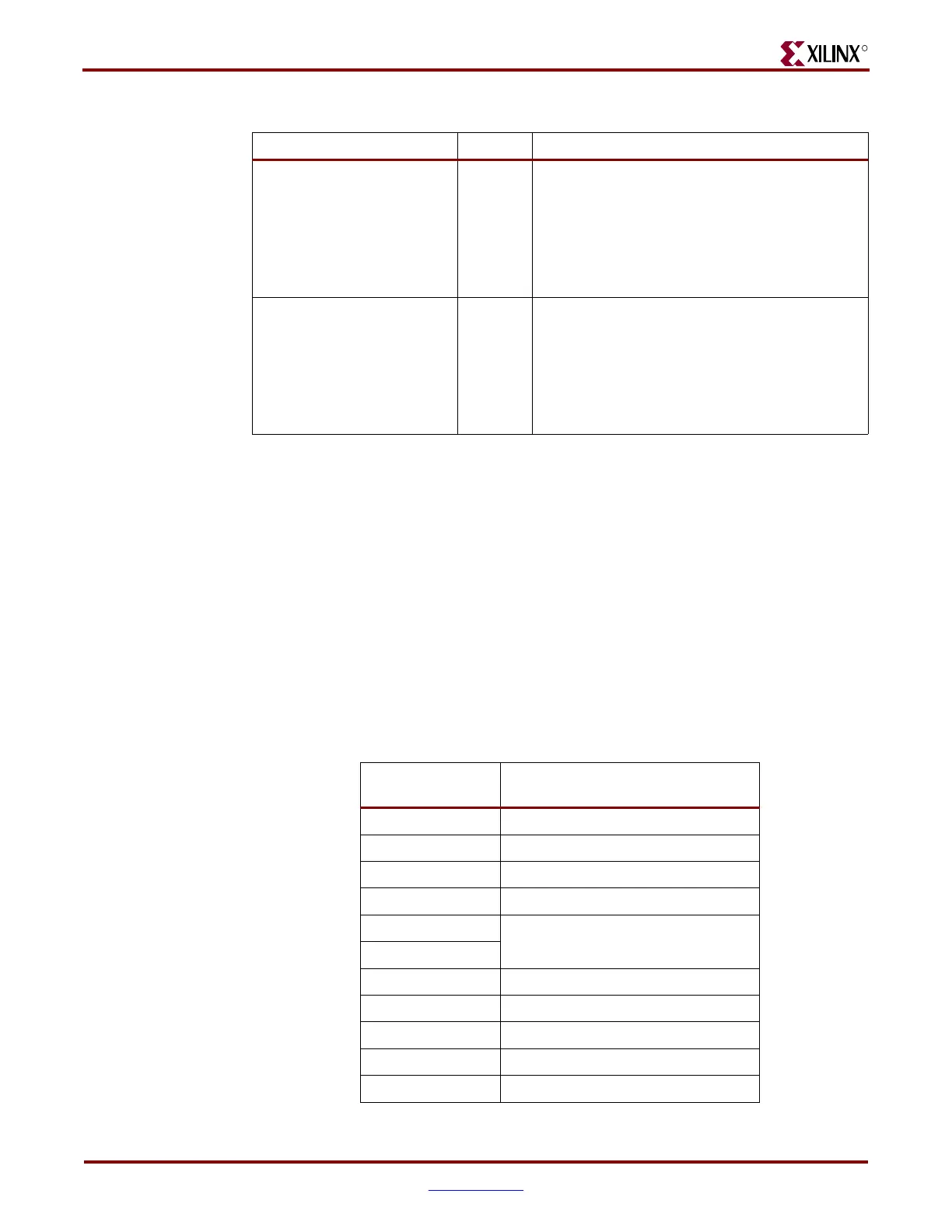
Configuration proceeds as shown in Table 7-11:
GTS_CYCLE
5:3
Startup cycle to deassert the Global Three-State
(GTS) signal.
001: Startup cycle 2
010: Startup cycle 3
011: Startup cycle 4
100: Startup cycle 5
101: Startup cycle 6
GWE_CYCLE
2:0
Startup phase to deassert the Global Write Enable
(GWE) signal.
001: Startup cycle 2
010: Startup cycle 3
011: Startup cycle 4
100: Startup cycle 5
101: Startup cycle 6
Table 7-10: Configuration Options Register Description (Continued)
Name Bit Index Description
Table 7-11: Configuration Sequence
Configuration
Data (hex)
Explanation
FFFFFFFF Dummy word
AA995566 Sync word
30008001 Type 1 write 1 words to CMD
00000007 RCRC command
20000000
NO-OP
20000000
30012001 Type 1 write 1 words to COR
XXXXXXXX Data word 0
30018001 Type 1 write 1 words to ID
0167C093 Device_ID
30008001 Type 1 write 1 words to CMD

 Loading...


