Virtex-4 FPGA Configuration User Guide www.xilinx.com 71
UG071 (v1.12) June 2, 2017
Boundary-Scan for Virtex-4 Devices Using IEEE Standard 1532
3. Load JSHUTDOWN.
4. Go to the RTI state and clock TCK at least 12 times to clock the shutdown sequence.
5. Proceed to the SHIFT-IR state and load the CFG_IN instruction again.
6. Go to the SHIFT-DR state and load the configuration bits. Make sure the configuration
bits contain the AGHIGH command, asserting the global signal GHIGH_B. This
prevents contention while writing configuration data.
0011 0000 0000 0000 1000 0000 0000 0001→ Header: Write to CMD
0000 0000 0000 0000 0000 0000 0000 1000→ AGHIGH command asserts GHIGH_B
0000 0000 0000 0000 0000 0000 0000 0000→ flush pipe
7. When all configuration bits have been loaded, reset the TAP by clocking five 1s on
TMS.
8. Go to the SHIFT-IR state and load the JSTART instruction.
9. Go to the RTI state and clock TCK at least 12 times to clock the startup sequence.
10. Go to the TLR state to complete the reconfiguration process.
Boundary-Scan for Virtex-4 Devices Using IEEE Standard 1532
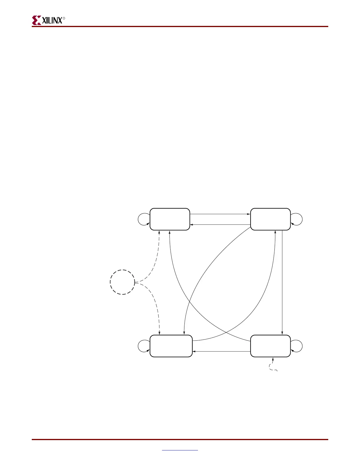
ISC Modal States
Once the device is powered up, it goes to the Unprogrammed state. The I/Os are all either
3-stated or pulled up. When ISC_ENABLE is successfully executed, the ISC_Enabled
signal is asserted, and the device moves to the ISC_Accessed state. When the device moves
Figure 3-8: ISC Modal States
Unprogrammed
(0,0)
Power
UP
ISC_ENABLE is executed
TLR & ISC_Done is clear
ISC_Accessed
(1,X)
Operational
(0,1)
ISC Complete
(0,X)
Any non-test instruction,
but ISC_ENABLE
executed
Any non-test instruction,
but ISC_ENABLE
executed
Any non-test instruction,
but ISC_DISABLE loaded
and ISC_DONE is set
Any non-test instruction,
but ISC_DISABLE loaded
and ISC_DONE is clear
TLR and
ISC_Done
is set
ISC_ENABLE
executed
(ISC_Enabled, ISC_Done)
ISC_Done is clear
ISC_Done is set
Any non-test
instruction, but
ISC_DISABLE
executed
ISC_DISABLE
loaded
ISC_DISABLE
executed
UG071_32_121803

 Loading...


