Virtex-4 FPGA Configuration User Guide www.xilinx.com 21
UG071 (v1.12) June 2, 2017
Startup (Step 8)
configuration data frames, causing incorrect design behavior, or even damaging the
device.
If a CRC error occurs during configuration, the device must be resynchronized and
reconfigured. In serial modes, the device can only be resynchronized by pulsing the
PROGRAM_B pin and restarting the configuration process from the beginning. In
SelectMAP modes, either the PROGRAM_B pin can be pulsed Low or an ABORT sequence
can be initiated (see “SelectMAP Configuration Interface” in Chapter 2).
Virtex-4 devices use a 32-bit CRC check. The CRC check is designed to catch errors in
transmitting the configuration bitstream. There is a scenario where errors in transmitting
the configuration bitstream can be missed by the CRC check:
Certain clocking errors, such as double-clocking, can cause loss of synchronization
between the 32-bit bitstream packets and the configuration logic. Once
synchronization is lost, any subsequent commands are not understood, including the
command to check the CRC. In this situation, configuration fails with DONE Low and
INIT_B High.
Virtex-4 configuration uses a standard CRC32C checksum algorithm. The CRC32C
polynomial is:
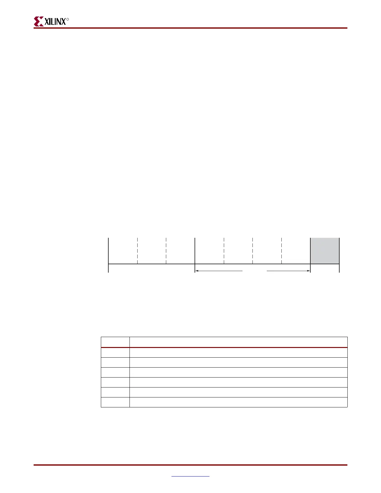
Startup (Step 8)
After the configuration frames are loaded, the bitstream instructs the device to enter the
startup sequence. The startup sequence is controlled by an 8-phase (phases 0–7) sequential
state machine. The startup sequencer performs the tasks outlined in Table 1-8.
The specific order of startup events (except for EOS assertion) is user-programmable
through BitGen options (refer to the Development System Reference Guide). Table 1-8 shows
the general sequence of events, although the specific phase for each of these startup events
is user-programmable (EOS is always asserted in the last phase). Refer to Chapter 2,
x
32
x
28
x
27
x
26
x
25
x
23
x
22
x
20
x
19
x
18
x
14
x
13
x
11
x
10
x
9
x
8
x
6
1+ + + + + + + + + + + + + ++++
Figure 1-10: Start-Up Sequence (Step 8)
Table 1-8: User-Selectable Cycle of Startup Events
Phase Event
1–6 Wait for DCMs to Lock (optional)
1–6 Wait for DCI to Match (optional)
1
–6 Assert GWE (Global Write Enable), allowing RAMs and flip-flops to change state
1–6 Negate GTS (Global 3-State), activating I/O
1–6Release DONE pin
7 Assert EOS (End Of Startup)
Device
Power-Up
Sample Mode
Pins
Synchronization
Device ID
Check
CRC Check
Clear
Configuration
Memory
Startup
Sequence
Load
Configuration
Data
Start
Finish
ug071_10_122105
Bitstream
Loading
Steps
12345678

 Loading...


