60 www.xilinx.com Virtex-4 FPGA Configuration User Guide
UG071 (v1.12) June 2, 2017
Chapter 3: Boundary-Scan and JTAG Configuration
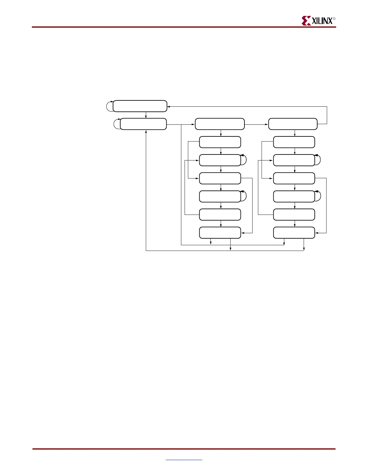
Capture-DR:
In this controller state, the data is parallel-loaded into the data registers selected by the
current instruction on the rising edge of TCK.
Shift-Dr, Exit1-DR, Pause-DR, Exit2-DR, and Update-DR:
These controller states are similar to the Shift-IR, Exit1-IR, Pause-IR, Exit2-IR, and Update-
IR states in the Instruction path.
Virtex-4 devices support the mandatory IEEE 1149.1 commands, as well as several Xilinx
vendor-specific commands. The EXTEST, INTEST, SAMPLE/PRELOAD, BYPASS,
IDCODE, USERCODE, and HIGHZ instructions are all included. The TAP also supports
internal user-defined registers (USER1, USER2, USER3, and USER4) and
configuration/readback of the device.
The Virtex-4 Boundary-Scan operations are independent of mode selection. The Boundary-
Scan mode in Virtex-4 devices overrides other mode selections. For this reason, Boundary-
Scan instructions using the Boundary-Scan register (SAMPLE/PRELOAD, INTEST, and
EXTEST) must not be performed during configuration. All instructions except the user-
defined instructions are available before a Virtex-4 device is configured. After
configuration, all instructions are available.
JSTART and JSHUTDOWN are instructions specific to the Virtex-4 architecture and
configuration flow.
For details on the standard Boundary-Scan instructions EXTEST, INTEST, and BYPASS,
refer to the IEEE Standard.
Figure 3-2: Boundary-Scan Tap Controller
1
ug071_34_121703
TEST-LOGIC-RESET
0
RUN-TEST/IDLE
1
SELECT-DR-SCAN
0
1
0
CAPTURE-DR CAPTURE-IR
0
1
0
0
SHIFT-DR SHIFT-IR
1
0
1
0
EXIT1-DR EXIT1-IR
0
1
0
PAUSE-DR PAUSE-IR
1
0
1
EXIT2-DR
1
EXIT2-IR
1
UPDATE-DR
1
UPDATE-IR
1
SELECT-IR-SCAN
0
1 0
0
0
1
1
0
NOTE: The value shown adjacent to each state transition in this figure
represents the signal present at TMS at the time of a rising edge at TCK.

 Loading...


