Virtex-4 FPGA Configuration User Guide www.xilinx.com 69
UG071 (v1.12) June 2, 2017
Boundary-Scan for Virtex-4 Devices Using IEEE Standard 1149.1
Single Device Configuration
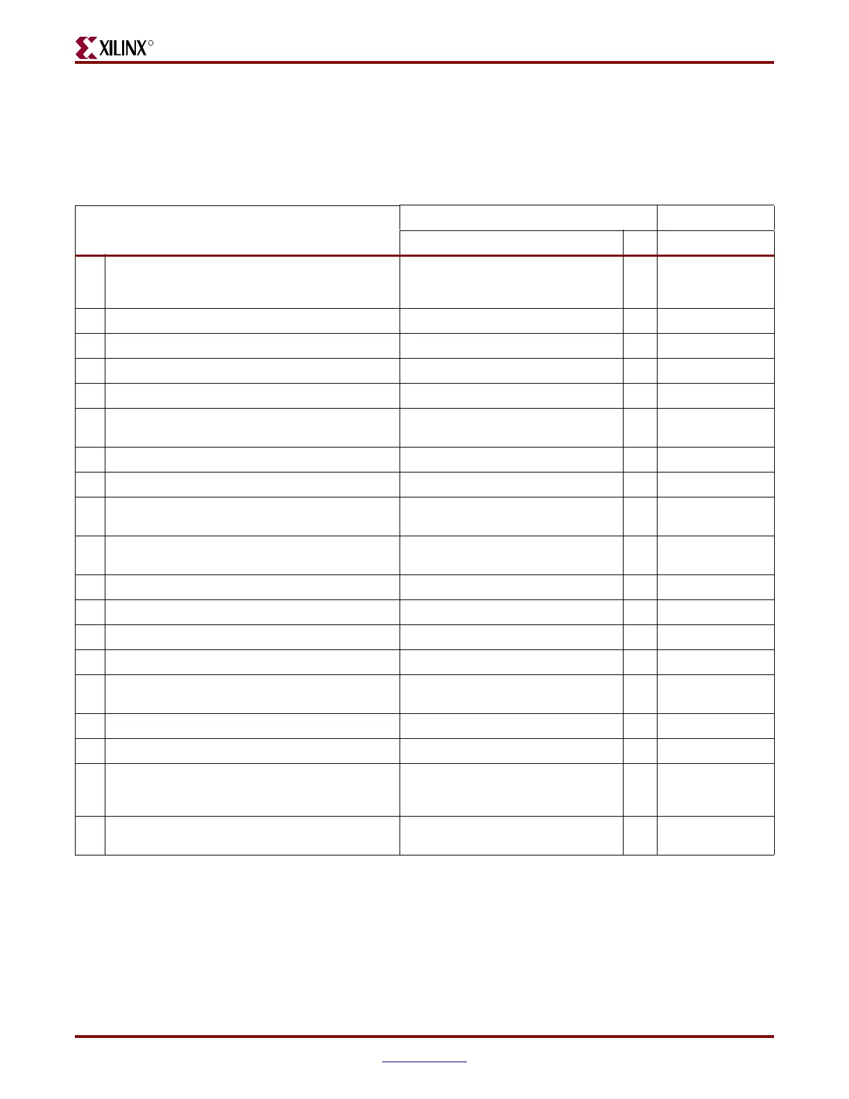
Table 3-6 describes the TAP controller commands required to configure a Virtex-4 device.
Refer to Figure 3-2 for TAP controller states. These TAP controller commands are issued
automatically if configuring the part with the iMPACT software.
Table 3-6: Single Device Configuration Sequence
TAP Controller Step and Description
Set & Hold # of Clocks
TDI TMS TCK
1. On power-up, place a logic 1 on the TMS, and clock
the TCK five times. This ensures starting in the TLR
(Test-Logic-Reset) state.
X15
2. Move into the RTI state. X01
3. Move into the SELECT-IR state. X12
4. Enter the SHIFT-IR state. X02
5. Start loading the CFG_IN instruction, LSB first: 111000101 0 9
6. Load the MSB of CFG_IN instruction when exiting
SHIFT-IR, as defined in the IEEE standard.
111
7. Enter the SELECT-DR state. X12
8. Enter the SHIFT-DR state. X02
9. Shift in the Virtex-4 bitstream. Bit
n
(MSB) is the first
bit in the bitstream
(1)
.
bit
1
... bit
n
0
(bits in
bitstream)-1
10. Shift in the last bit of the bitstream. Bit
0
(LSB) shifts
on the transition to EXIT1-DR.
bit
0
11
11. Enter UPDATE-DR state. X11
12. Reset TAP by clocking five 1s on TMS X15
13. Enter the SELECT-IR state. X12
14. Move to the SHIFT-IR state. X02
15. Start loading the JSTART instruction. The JSTART
instruction initializes the startup sequence.
111001100 0 9
16. Load the last bit of the JSTART instruction. 111
17. Move to the UPDATE-IR state. X11
18. Move to the RTI state and clock the startup
sequence by applying a minimum of 12 clock cycles
to the TCK.
X012
19. Move to the TLR state. The device is now
functional.
X13
Notes:
1. In the Configuration Register, data is shifted in from the right (TDI) to the left (TDO), MSB first. (Shifts into the Configuration Register are
different from shifts into the other registers in that they are MSB first.)

 Loading...


