17
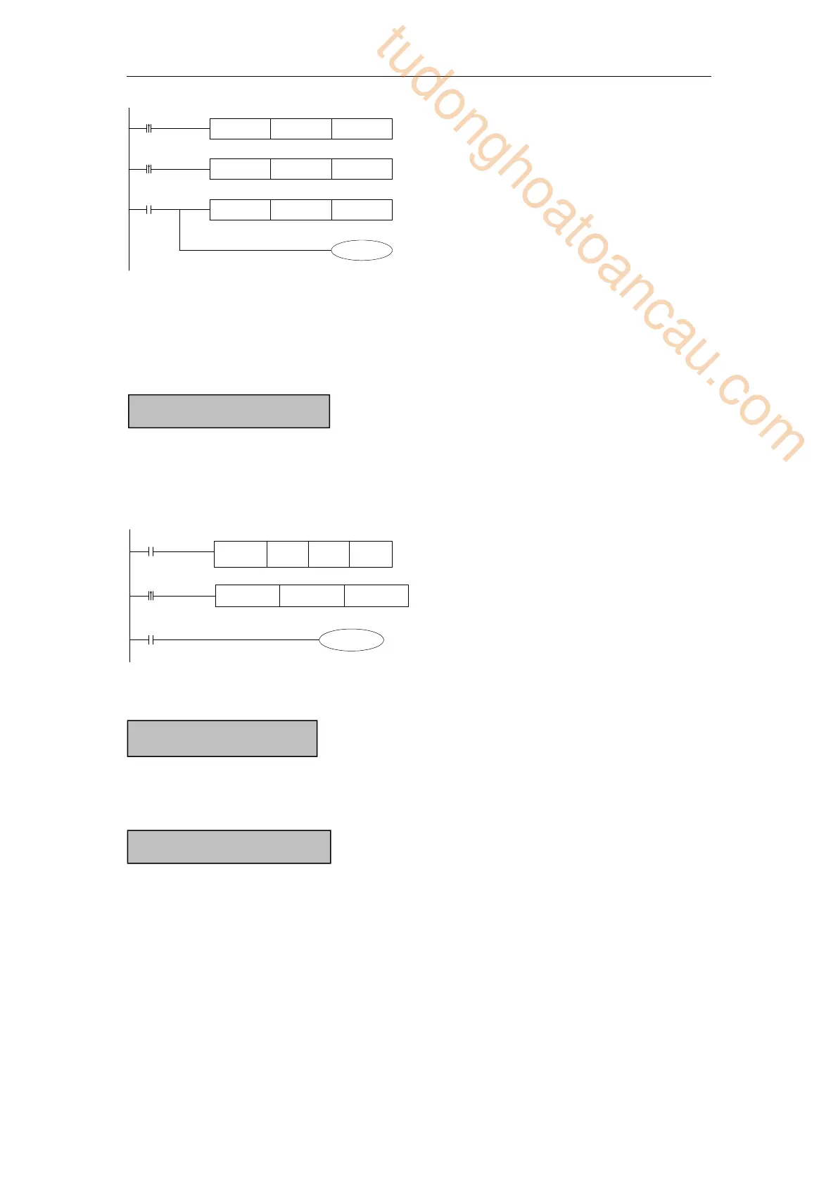
MOV D10[D0] D100
SM0
M2
Y0[D0]
MOV K5 D0
SM2
MOV K0 D0
When D0=0, D100=D10, Y0 is ON.
When M2 turns from OFF to ON, D0=5, then D100=D15, Y5 is ON.
Therein, D10[D0]=D[10+D0], Y0[D0]=Y[0+D0].
The word offset combined by bit: DXn[Dm] represents DX[n+Dm].
The soft components with offset, the offset can represent by soft component D, HD.
For common usage,16 bits, represent the current value of timer/counter;
For common usage,32 bits, (combine two continuous16 bits registers)
To represent them, just use the letter+address method, such as T10, C11, HT10, HC11.
E.g.
MOV D0T11
M0
T11
Y1
X0
TMR T11 K99 K100
In the above example, MOV T11 D0, T11 represents word register;
LD T11, T11 represents bit register.
For power off retentive usage,16 bits
For power off retentive usage,32 bits, (combine two continuous16 bits registers)
For special usage, occupied by the system, can’t be used as common instruction parameters
For common usage,16 bits, (combine16 bits)
The soft components which can be combined to words are: X, Y, M, S, T, C, HM, HS, HT,
HC.
Format: add “D” in front of soft components, like DM10, represents a 16-bits register from
M10~M25 .
Get16 bits beginning from DXn, cannot beyond the soft components range;
The word combined by bits cannot do bit addressing;
E.g.:
Timer T, HT/Counter C, HC
Register combined by bits
tudonghoatoancau.com
 Loading...