Home
Xinje
Network Hardware
XDH Series
Xinje XDH Series User Manual
5
of 1
of 1 rating
456 pages
Give review
Manual
Specs
To Next Page
To Next Page
To Previous Page
To Previous Page
Loading...
86
C
J
P
6
X
0
(
)
Y
0
X
1
(
)
T
2
4
6
R
X
2
T
M
R
T
2
46
K
1
0
00
K
10
X
3
M
O
V
K
3
D
0
X
4
P
6
C
J
P7
X
0
(
)
Y
0
X
5
P
7
(
)
T
2
4
6
R
X
6
4-3-2
Call
su
broutine
[CALL]
and
Subroutine
return
[SRET]
1)Summary
Call
the
prog
rams
which
need
to
be
executed
tog
ether,
decrease
the
prog
ram's
steps;
Subroutine
Call
[CALL
]
16
bits
CALL
32
bits
-
Execution
condi
tion
Normally
ON/OFF,
Rising/Falling
edge
Suitable
Mode
ls
XD,
XL
Hardware
requ
irement
-
Software
requirem
ent
-
Subroutine
Return
[SRET]
16
bits
SRET
32
bits
-
Execution
condi
tion
-
Suitable
Mode
ls
XD,
XL
Hardware
requ
irement
-
Software
requirem
ent
-
2)Operands
Operands
Function
Data
Type
Pn
Jump
to
the
target
(with
poin
ter
No.)
P
(P0~P9999)
Pointer's
No.
3)
Suitable
Soft
Components
Others
Pointer
P
I
●
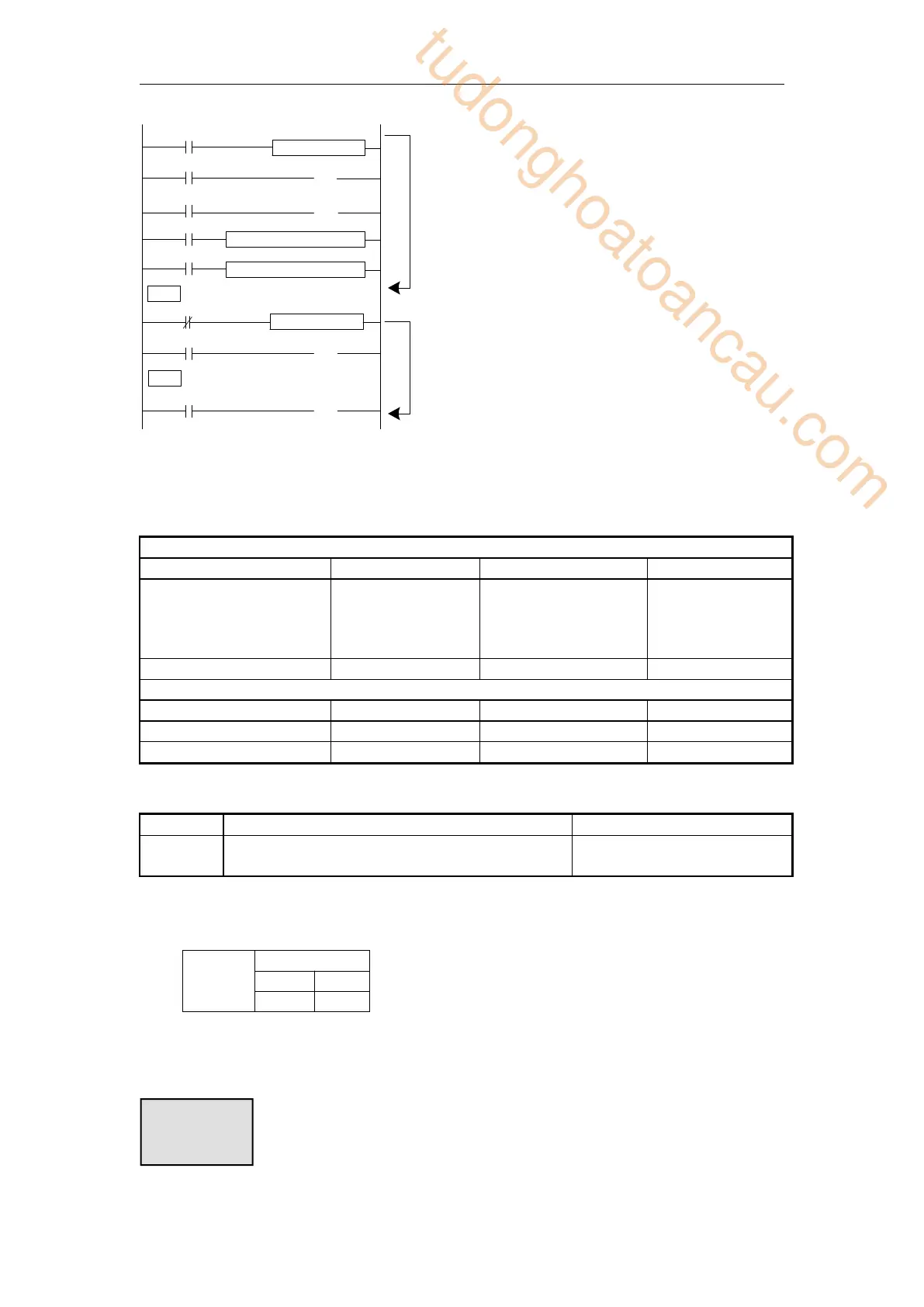
In
the
left
graph,
Y0
becomes
to
be
dual
coil
output,
but
when
X0=OFF,
X1
activates;
when
X0=ON,
X5
activates
CJ
ca
n’t
jum
p
from
one
STL
to
another
STL;
Aft
er
dr
iving
timer
T0~T575,
HT0~HT79
5
and
HSC0~H
SC30,
if
executes
CJ,
continue
working,
the
output
activates.
The
Tag
must
be
match
when
using
CJ
instruction.
Description
tudonghoatoancau.com
86
88
Table of Contents
1 Programming Summary
11
1-1 PLC Features
11
1-2 Programming Language
12
1-2-1 Type
12
1-2-2 Alternation
12
1-3 Programming mode
13
2 Soft Component Function
14
2-1 Summary of the Soft Components
14
2-2 Structure of Soft Components
17
2-2-1 Structure of Memory
17
2-2-2 Structure of Bit Soft Components
19
2-3 Soft Components List
20
2-3-1 Soft Components List
20
2-4 Input/output relays (X, Y)
37
2-5 Auxiliary Relay (M, HM, SM)
39
2-6 Status Relay (S, HS)
40
2-7 Timer (T, HT)
41
2-8 Counter ( C, HC, HSC)
44
2-9 Data register (D, HD, SD, HSD)
49
2-9-1 Word consist of bits
52
2-9-2 Offset application
53
2-10 Flash register (FD, SFD, FS)
54
2-11 Constant
55
2-12 Programming principle
56
3 Basic Program Instructions
60
3-1 Basic Instructions List
60
3-2 [LD] , [LDI] , [OUT]
62
3-3 [AND] , [ANI]
63
3-4 [OR] , [ORI]
64
3-5 [LDP] , [LDF] , [ANDP] , [ANDF] , [ORP] , [ORF
65
3-6 [LDD] , [LDDI] , [ANDD] , [ANDDI] , [ORD] , [O
67
3-7 [ORB]
68
3-8 [ANB]
69
3-9 [MCS] , [MCR]
69
3-10 [ALT]
70
3-11 [PLS] , [PLF]
71
3-12 [SET], [RST]
72
3-13 [CNT],[CNT_D],[DCNT],[DCNT_D],[RST]for the co
73
3-14 [TMR], [TMR_A] for timers
75
3-15 [END]
76
3-16 [GROUP] , [GROUPE]
77
3-17 Programming notes
77
4 Applied Instructions
79
4-1 Applied Instructions List
79
4-2 Reading Method of Applied Instructions
83
4-3 Program Flow Instructions
86
4-3-1 Condition Jump [CJ]
86
4-3-2 Call subroutine [CALL] and Subroutine return
87
4-3-3 Flow [SET], [ST], [STL], [STLE]
89
4-3-4 [FOR] and [NEXT]
94
4-3-5 [FEND] and [END]
96
4-4 Data compare function
98
4-4-1 LD Compare [LD]
98
4-4-2 Serial Compare [AND]
99
4-4-3 Parallel Compare [OR]
101
4-5 Data Move Instructions
103
4-5-1 Data Compare [CMP, DCMP, QCMP]
103
4-5-2 Data zone compare [ZCP, DZCP]
104
4-5-3 MOV [MOV, DMOV, QMOV]
105
4-5-4 Data block Move [BMOV]
107
4-5-5 Data block Move [PMOV]
109
4-5-6 Fill Move [FMOV, DFMOV]
110
4-5-7 Floating move [EMOV, EDMOV]
111
4-5-8 FlashROM Write [FWRT, DFWRT, QFWRT]
113
4-5-9 Zone set [MSET]
114
4-5-10 Zone reset [ZRST]
115
4-5-11 Swap the high and low byte [SWAP]
116
4-5-12 Exchange [XCH, DXCH]
117
4-6 Data Operation Instructions
119
4-6-1 Addition [ADD, DADD, QADD]
119
4-6-2 Subtraction [SUB]
122
4-6-3 Multiplication [MUL, DMUL, QMUL]
123
4-6-4 Division [DIV, DDIV, QDIV]
125
4-6-5 Increment [INC, DINC, QINC] & Decrement [DEC
127
4-6-6 Mean [MEAN, DMEAN]
129
4-6-7 Logic AND [WAND, DWAND], Logic OR[WOR, DWOR]
130
4-6-8 Logic converse [CML, DCML]
132
4-6-9 Negative [NEG, DNEG]
133
4-7 Shift Instructions
134
4-7-1 Arithmetic shift left [SHL,DSHL], Arithmetic
134
4-7-2 Logic shift left [LSL], Logic shift right [L
136
4-7-3 Rotation shift left [ROL,DROL], Rotation shi
137
4-7-4 Bit shift left [SFTL]
139
4-7-5 Bit shift right [SFTR]
140
4-7-6 Word shift left [WSFL]
141
4-7-7 Word shift right [WSFR]
142
4-8 Data Convert
143
4-8-1 Single word integer converts to double word
144
4-8-2 32 bits integer to 64 bits integer batch con
145
4-8-3 Integer converts to float point [FLT, DFLT,F
147
4-8-4 Integer to double precision floating point[D
148
4-8-5 Float point converts to integer [INT, DINT]
149
4-8-6 Double - precision floating point to intege
150
4-8-7 Single precision floating point to double pr
151
4-8-8 Single precision floating point to double pr
152
4-8-9 BCD convert to binary [BIN]
153
4-8-10 Binary convert to BCD [BCD]
155
4-8-11 Hex converts to ASCII [ASCI]
156
4-8-12 ASCII convert to Hex [HEX]
158
4-8-13 Coding [DECO]
159
4-8-14 High bit coding [ENCO]
161
4-8-15 Low bit coding [ENCOL]
163
4-8-16 Binary to Gray code [GRY]
166
4-8-17 Gray code to binary [GBIN,DGBIN]
167
4-9.Floating number Operation
168
4-9-1 Floating Compare [ECMP,EDCMP]
168
4-9-2 Floating Zone Compare [EZCP]
170
4-9-3 Floating Addition[EADD,EDADD]
171
4-9-4 Floating Subtraction[ESUB,EDSUB]
173
4-9-5 Floating Multiplication[EMUL,EDMUL]
175
4-9-6 Floating Division[EDIV,EDDIV]
176
4-9-7 Float Square Root [ESQR]
178
4-9-8 Sine[SIN]
179
4-9-9 Cosine[COS]
180
4-9-10 TAN [TAN]
181
4-9-11 ASIN [ASIN]
182
4-9-12 ACOS [ACOS]
183
4-9-13 ATAN [ATAN]
184
4-10 RTC Instructions
185
4-10-1 Read the clock data [TRD]
186
4-10-2 Write Clock Data [TWR]
187
4-10-3 Accurate clock BD board data read [MOV]
189
4-10-4 Accurate clock BD board data write [TO]
190
4-10-5 Clock data add [TADD]
192
4-10-6 Clock data sub [TSUB]
193
4-10-7 Convert hour, minute, and second data to se
195
4-10-8 Convert second data to hours, minutes, and
196
4-10-9 Clock compare [TCMP]
197
4-10-10 Date (year, month, day) compare [DACMP]
198
5 HIGH SPEED COUNTER (HSC)
201
5-1 Functions Summary
201
5-2 HSC Mode
202
5-3 HSC Range
204
5-4 HSC Input Wiring
204
5-5 HSC ports assignment
205
5-6 AB phase counting frequency doubling setting
210
5-7 HSC instruction
211
5-7-1 Single phase HSC [CNT]
211
5-7-2 AB phase HSC [CNT_AB]
212
5-7-3 HSC reset [RST]
213
5-7-4 Read HSC value [DMOV]
214
5-7-5 Write HSC value [DMOV]
215
5-7-6 The difference between HSC and normal counte
216
5-8 HSC Example
216
5-9 HSC interruption
218
5-9-1 Function overview and panel configuration
218
5-9-2 Single phase 100-segment HSC [CNT]
220
5-9-3 AB phase 100-segment HSC[CNT_AB]
221
5-9-4 Interruption flag of HSC
223
5-9-5 Setting value meaning in absolute or relativ
223
5-9-6 HSC interruption cycle mode
226
5-9-7 CAM function of high speed counter interrupt
227
5-9-8 Interruption using notes and parameter addre
228
5-9-9 Application of HSC interruption
229
6 Communication Function
234
6-1 Summary
234
6-1-1 COM port
234
6-1-2 Communication parameters
243
6-2 MODBUS communication
244
6-2-1 Function overview
244
6-2-2 Changing of Modbus instruction
245
6-2-3 Modbus communication address
245
6-2-4 Modbus data format
256
6-2-5 Communication Instructions
262
6-2-6 Modbus serial port configuration
271
6-2-7 Modbus Communication application
275
6-2-8 Application
277
6-3 Free communication
280
6-3-1 Free communication mode
280
6-3-2 Serial port configuration
281
6-3-3 Suitable occasion
283
6-3-4 Free communication instruction
283
6-3-5 Free communication example
287
6-4 Communication flag and register
293
6-5 Read write serial port parameters
297
6-5-1 Read serial port parameters [CFGCR]
297
6-5-2 Write serial port parameters [CFGCW]
298
6-5-3 Serial port parameter name and setting
299
7 PID Control Function
301
7-1 PID Introduction
301
7-2 Instruction Form
301
7-3 Parameters setting
303
7-3-1 Register and their functions
304
7-3-2 Parameters Description
308
7-4 Auto Tune Mode
310
7-5 Advanced Mode
313
7-6 Application outlines
314
7-7 Application
314
8 C Language Function Block
320
8-1 Summary
320
8-2 Instruction Format
320
8-3 Operation Steps
321
8-4 Import and Export the Functions
324
8-5 Edit the Func Blocks
325
8-6 Program Example
327
8-7 New functions
330
8-8 Function library
332
8-8-1 New function
333
8-8-1-1 Classification of Libraries
333
8-8-2 Basic functions
333
8-8-2-1 Open and save file
333
8-8-3 Newly build
333
8-8-3-1 Create project library
333
8-8-3-2 Create global library
334
8-8-3-3 Create new source
335
8-8-3-4 Create new header
337
8-8-4 Edit
337
8-8-4-1 Edit library information
337
8-8-4-2 Source file information
339
8-8-4-3 Header file information
339
8-8-5 Export
340
8-8-5-1 Export the function library
340
8-8-5-2 Export source/header file
340
8-8-6 Import
341
8-8-6-1 Import the function library
341
8-8-6-2 Import function files
342
8-8-7 Other functions
342
8-8-7-1 Library manger
342
8-8-7-2 Delete library file
343
8-8-7-3 Remove library file
344
8-8-7-4 Delete source/header file
344
8-8-7-5 Transfer
345
8-8-7-6 Compile
346
8-8-7-7 Set Global Library Directory
347
8-9 Application notes
348
8-10 Q&A of C language
351
8-11 Function Table
353
9 Sequence BLOCK
357
9-1 Concept of the BLOCK
357
9-2 Call the BLOCK
358
9-2-1 Add the BLOCK
358
9-2-2 Move the BLOCK
361
9-2-3 Delete the BLOCK
362
9-2-4 Modify the BLOCK
362
9-3 Edit the instruction of the BLOCK
363
9-3-1 Command item
363
9-3-2 Pulse Item
365
9-3-3 Wait Item
366
9-3-4 Module Read and Write(FROM/TO)instruction
367
9-4 Running form of the BLOCK
368
9-5 BLOCK instruction editing rules
370
9-6 BLOCK related instructions
372
9-6-1 Instruction explanation
372
9-6-2 The timing sequence of the instructions
374
9-7 BLOCK flag bit and register
378
10 Special Function Instructions
379
10-1 Pulse Width Modulation [PWM]
379
10-2 Frequency measurement [FRQM]
383
10-3 Precise Timing [STR]
386
10-4 Interruption [EI], [DI], [IRET]
391
10-4-1 External Interruption
391
10-4-2 Timing Interruption
397
10-5 SD card reading and writing
399
10-5-1 Document content and format
399
10-5-2 File name and storage location
400
10-5-3 Read/write SD card
400
10-5-4 Notes
401
10-5-5 Instructions for format conversion tool
403
10-6 Multi station control[MSC]
405
11 Common Questions and Answers
412
Q1:How to connect PLC with PC?
412
Q2:PC cannot connect PLC via RS232 port, it shows
415
Q3:XD/XL series PLC system upgrade
417
Q4: The bit soft component function.
422
Q5: What’s the use of execution instruction LDD/OU
423
Q6: Why the output LED keeps flashing when using A
423
Q7: Why the M and Y cannot output sometime?
423
Q8: Check and change the button battery in the PCB
424
Q9: Communicate with SCADA software
424
Q10: MODBUS Communication
424
Q11: The LED light of XD/XL series PLC (PWR/RUN/ER
424
Q12: The result is not correct when doing floating
425
Q13: Why the floating numbers become messy code in
425
Q14: Why data errors after using DMUL instructions
426
Q15: Why the output point action errors after PLC
426
Q16: Why expansion module does not work while powe
426
Q17: Why the signal input but cannot see the high
426
Q18: C language advantages compared to ladder char
427
Q19: What’s PLC output terminal A, B?
427
Q20: What’s the difference of sequence function BL
427
Q21: What are the download modes of XD/XL series P
427
Q22: What kinds of confidentiality methods do XD/X
428
Q23: What’s the advantage that XD series PLC repla
428
Q24: PLC I/O terminalexchanging
429
Q25: What’s the function of XD/XL series PLC indir
430
Q26: How does XD/XL series PLC connect to the netw
430
Q27: How to add soft element andline note in XDppr
430
Q28: Do not have clock function?Why is the clock i
432
Appendix Special soft components
433
Appendix 1 Special Auxiliary Relay
433
Appendix 2 Special Data Register
439
Appendix 3 Special Flash Register
448
Appendix 4 PLC resource conflict table
452
Appendix 5 PLC function configuration list
453
5
Based on 1 rating
Ask a question
Give review
Questions and Answers:
Need help?
Do you have a question about the Xinje XDH Series and is the answer not in the manual?
Ask a question
Xinje XDH Series Specifications
General
Brand
Xinje
Model
XDH Series
Category
Network Hardware
Language
English
Related product manuals
Xinje VH5 Series
76 pages