256
(1) Take 06H function code as example (single register write), and introduce data format.
E.g.: upper computer write data to PLC H0002 (D2).
RTU mode:
Explanation:
1. Address is PLC station no.
2. Function code is Modbus-RTU protocol read/write code.
3. Register address is the PLC modbus address, please see chapter 6-2-3.
4. Data content is the value in D2.
5. CRC CHECK High / CRC CHECK Low is high and low bit of CRC check value.
If 2 pieces of Xinje XD3 series PLC communicate with the other one, write K5000 to D2.
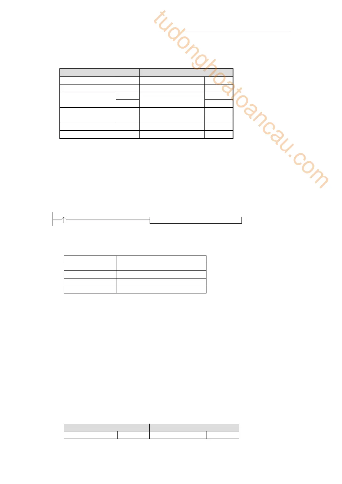
M 0
R E G W K 1 H 0 0 0 2 K 5 0 0 0 K 2
M0 is trigger condition (Rising edge). If communication fails, the instruction will try twice. If
the third time communication fails, then communication ends.
The relationship between REGW and Modbus RTU protocol (other instructions are the same)
The complete communication datum are: 01H 06H 00H 02H 13H 88H (system take CRC
checking automatically)
If monitor the serial port2 data by serial port debugging tool, the datum are: 01 06 00 02 13
88 25 5C
Note: The instruction doesn’t distinguish decimal, hex, binary, octal etc. For example,
B10000, K16 and H10 are the same value, so the following instructions are the same.
REGW K1 B111110100 D1 K2
REGW K1 K500 D1 K2
REGW K1 H1F4 D1 K2
(2) Function code 01H/02H: read coil/read input coil
Eg. Read coil address 6000H (Y0). At this time, Y0 and Y1 are ON.
RTU mode:
tudonghoatoancau.com
 Loading...