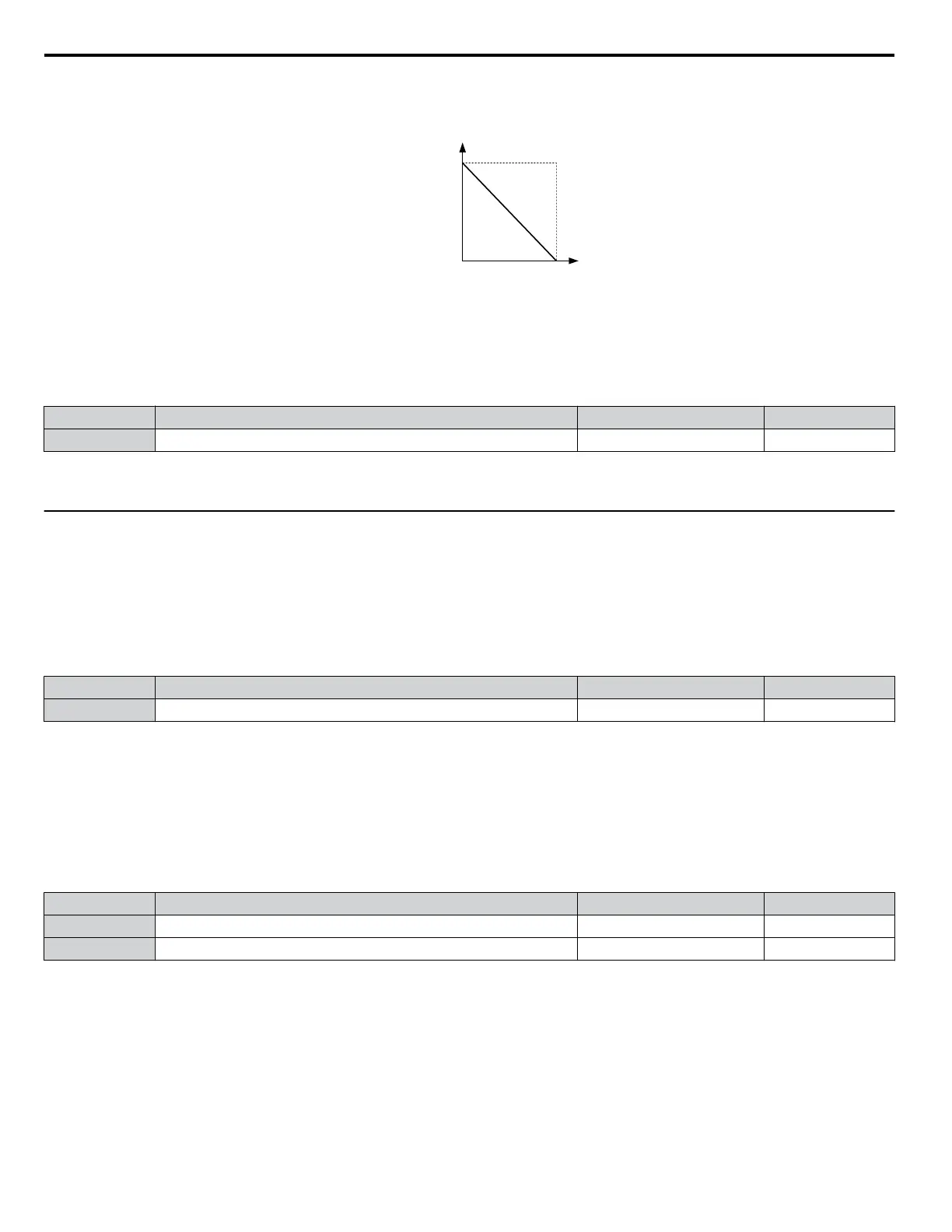
• Gain = 0%, Bias = 100%, A1 as frequency reference input
This setting leads to an inverse-acting frequency reference. The minimum analog input level (0 Vdc) will produce a 100%
frequency reference and the maximum analog input level (10 Vdc) will produce a 0% frequency reference.
0 V 10 V
Gain = 0 %
Bias = 100 %
Frequency
reference
Figure 5.31 Frequency Reference Setting by Analog Input with Inverse Gain and Bias Settings
n
H3-13: Analog Input Filter Time Constant
Parameter
H3-13 sets the time constant for a first order filter that will be applied to analog input A1 and also to the reference
value from potentiometer option (AI-V3/J).
No. Name Setting Range Default
H3-13 Analog Input Filter Time Constant 0.00 to 2.00 s 0.03 s
An analog input filter can be used to prevent erratic drive control when a “noisy” analog reference is used. The drive operation
becomes more stable the longer the time programmed, but it becomes less responsive to rapidly changing analog signals.
u
H4: Multi-Function Analog Output Terminal AM
These parameters assign a function to analog output terminal AM for monitoring a specific aspect of drive performance.
n
H4-01: Multi-Function Analog Terminal AM Monitor Selection
Sets the desired drive monitor parameter Uo-oo to output as an analog value via terminal AM. Refer to U: Monitors on
page 201 for a list of all monitors. The “Analog Output Level” columns indicates if a monitor can be applied for analog output.
Example: Enter “103” for U1-03.
No. Name Setting Range Default
H4-01 Multi-Function Analog Terminal AM Monitor Selection 000 to 999 102
A setting of 031 or 000 applies no drive monitor to the analog output. With this setting the terminal AM output level can be
set by a PLC via a MEMOBUS/Modbus communications interface (through mode).
n
H4-02/H4-03: Multi-Function Analog Output Terminal AM Gain/Bias
Parameter H4-02 sets the output voltage that is equal to 100% of the monitor value. Parameter H4-03 sets the output voltage
equal to 0% of the monitor value.
Both values are set as a percentage of 10 V. The minimum output voltage for terminal AM is 0 V, the maximum is 10 Vdc.
Figure 5.32 illustrates the function of the gain and bias settings.
No. Name Setting Range Default
H4-02 Multi-Function Analog Output Terminal AM Gain -999.9 to 999.9% 100.0%
H4-03 Multi-Function Analog Output Terminal AM Bias -999.9 to 999.9% 0.0%
5.6 H: Terminal Functions
110
YASKAWA ELECTRIC SIEP C710606 31B YASKAWA AC Drive – J1000 Technical Manual
http://nicontrols.com
 Loading...


