u
Installation Orientation and Spacing
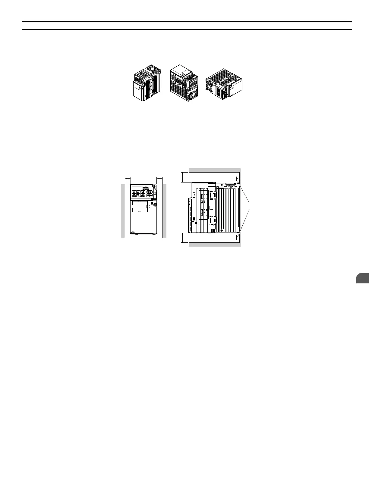
Install the drive upright as illustrated in Figure 2.1 to maintain proper cooling.
A
B
B
A – Correct B – Incorrect
Figure 2.1 Correct Installation Orientation
n
Single Drive Installation
Figure 2.2 explains the required installation spacing to maintain sufficient space for airflow and wiring. Install the heatsink
against a closed surface to avoid diverting cooling air around the heatsink.
A
A
C
C
B
Side Clearance
Top/Bottom Clearance
A – 30 mm minimum
B – Airflow direction
C – 100 mm minimum
Figure 2.2 Correct Installation Spacing
Note: The
space required on the left and right sides of the drive are the same for IP20/Open-Chassis drives and IP20/NEMA Type 1 drives using
the NEMA Type 1 Kit option.
n
Multiple Drive Installation
When installing multiple drives into the same enclosure panel, mount the drives according to Figure 2.2. When mounting
drives with a minimum side-by-side clearance of 2 mm according to Figure 2.3, derating must be considered and parameter
L8-35 must be set. Refer to Parameter List on page 187.
2.2 Mechanical Installation
YASKAWA ELECTRIC SIEP C710606 31B YASKAWA AC Drive – J1000 Technical Manual
27
2
Mechanical Installation
http://nicontrols.com

 Loading...


