C.7 Communications Timing
To prevent overrun in the slave drive, the master should wait a certain time between sending messages to the same drive. In
the same way, the slave drive must wait before sending response messages to prevent an overrun in the master. This section
explains the message timing.
u
Command Messages from Master to Drive
In order to prevent overrun and data loss, the master must wait between receiving a response and sending the same type of
command as before to the same slave drive. The minimum wait time depends on the command as shown in the table below.
Table C.2
Minimum Wait Time for Sending Messages
Command Type Example Minimum Wait Time
1
• Control command (Run, Stop)
•
Set inputs/outputs
• Read monitors and parameter values
10 ms
2 • Write parameters
50 ms
<1>
3 • Save changes using an Enter command
3 to 5 s
<1>
<1> If the drive receives command type 1 data during the minimum wait time, it will perform the command and then respond. However, if it receives
a command type 2 or 3 during that time, either a communication error will result or the command will be ignored.
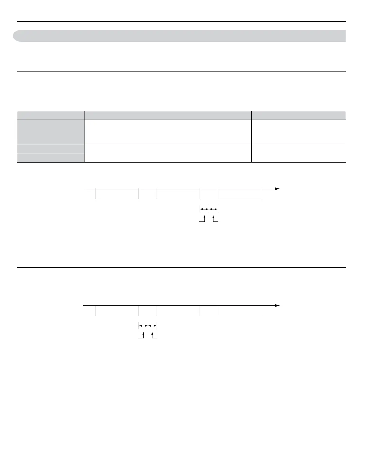
Command message Response message Command message
PLC→Drive PLC→DriveDrive→PLC
24 bit length
Master Send
Wait Time
Time
Figure C.7 Minimum Wait Time for Sending Messages
A timer should be set in the master to check how long it takes for the slave drive(s) to respond to the master. If no response
is received within a certain amount of time, the master should try resending the message.
u
Response Messages from Drive to Master
If the drive receives a command from the master, it will process the data received and wait for the time set in H5-06 until it
responds. Increase H5-06 if the drive response causes overrun in the master.
Time
Command message Response message Command message
PLC→Drive PLC→DriveDrive→PLC
24 bit length
H5-06
setting
Figure C.8 Minimum Response Wait Time
C.7 Communications Timing
218
YASKAWA ELECTRIC SIEP C710606 31B YASKAWA AC Drive – J1000 Technical Manual
http://nicontrols.com

 Loading...


