NOTICE: Do
not connect electromagnetic switches or MCs to the output motor circuits without proper sequencing. Improper sequencing of
output motor circuits may cause damage to the drive.
NOTICE: Install an MC on the input side of the drive when the drive should not automatically restart after power loss. To get the full
performance life out of the electrolytic capacitors and circuit relays, refrain from switching the MC more than once every 30 minutes. Frequent
use can damage the drive. Use the drive to stop and start the motor.
Note: 1. Install an MC to the drive output to prevent the drive from restarting automatically when the power is restored after momentary power
loss.
2. Set up a delay for the MC so that it does not open prematurely for the drive to continue operating through momentary power loss.
n
Protecting the Braking Resistor or Braking Resistor Unit
Use an MC on the input side of the drive to protect a braking resistor or braking resistor unit from overheat or fire.
WARNING! Fire Hazard. When using a braking unit, use a thermal relay on the braking resistors and configure a fault contact output for the
braking resistor unit to disconnect drive main power via an input contactor. Inadequate braking circuit protection could result in death or
serious injury by fire from overheating resistors.
u
Connecting an AC Reactor or DC Link Choke
AC reactors and DC link chokes suppress surges in current and improve the power factor on the input side of the drive.
Use an AC reactor, DC link choke, or both:
• To suppress harmonic current or improve the power factor of the power supply.
• When using a phase advancing capacitor switch.
• With a large capacity power supply transformer (over 600 kVA).
Note: Use an AC reactor or DC link choke when also connecting a thyristor converter (such as a DC drive) to the same power supply system,
regardless of the conditions of the power supply.
n
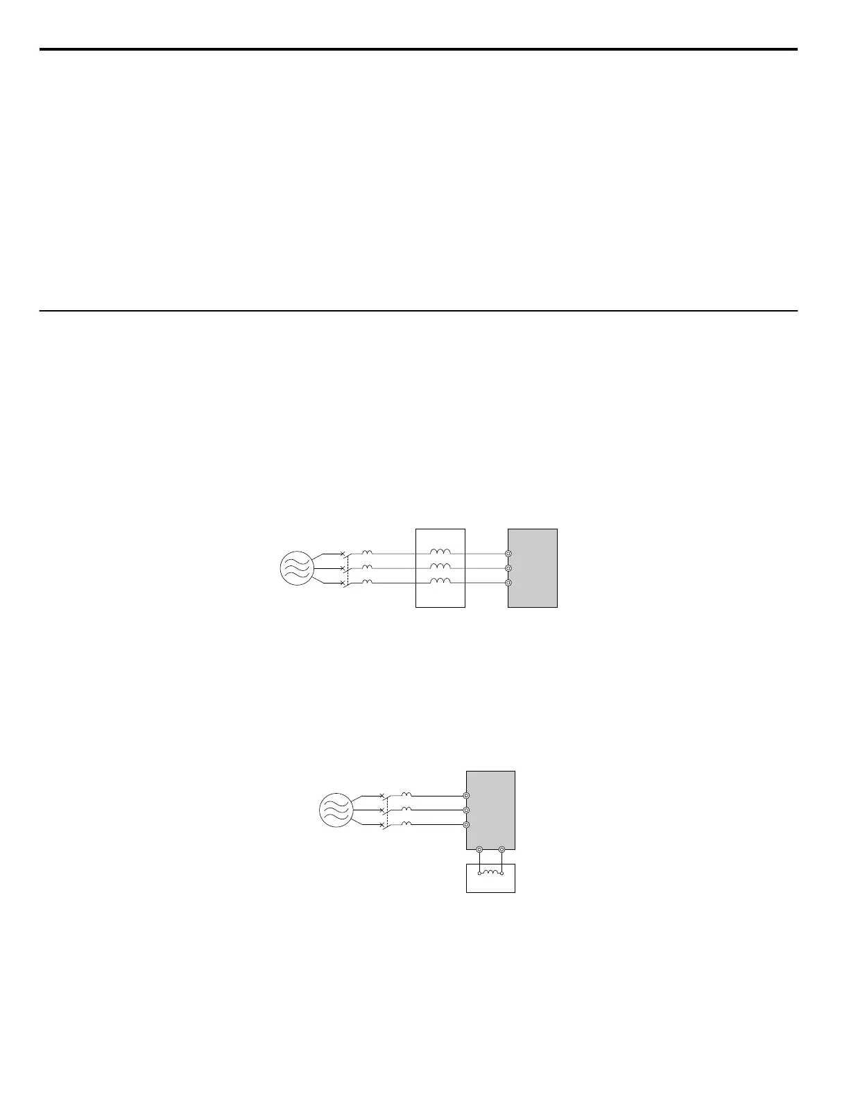
Connecting an AC Reactor
BA
C D
R/L1U
V
W
X
Y
Z
S/L2
T/L3
A – Power supply
B – MCCB
C – AC reactor
D – Drive
Figure 8.3 Connecting an AC Reactor
n
Connecting a DC Link Choke
Ensure
the jumper between terminals +1 and +2 (terminals are jumpered for shipment) is removed when connecting a DC link
choke. The jumper must be installed if no DC link choke is used. Refer to Connecting a DC Link Choke on page 168 for an
example of DC link choke wiring.
A
C
D
R/L1
+1 +2
B
S/L2
T/L3
A – Power supply
B – MCCB
C – Drive
D – DC link choke
Figure 8.4 Connecting a DC Link Choke
8.4 Installing Peripheral Devices
168
YASKAWA ELECTRIC SIEP C710606 31B YASKAWA AC Drive – J1000 Technical Manual
http://nicontrols.com
 Loading...


