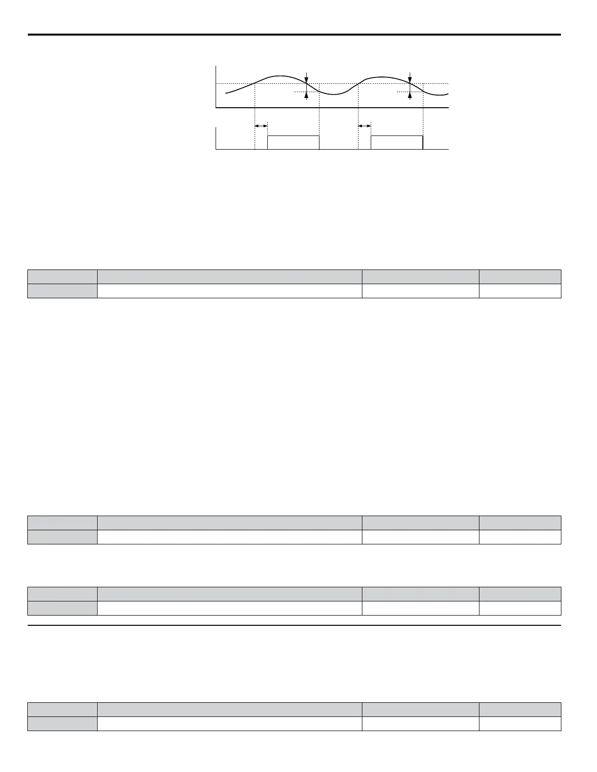
Motor current / torque
L6-02
10 % hysteresis
Torque detection (NO)
L6-03
ON
L6-03
10 % hysteresis
ON
Figure 5.37 Overtorque Detection Operation
Note: The torque detection function uses a hysteresis of 10% of the drive rated output current/motor rated torque.
Note: When overtorque occurs in the application, the drive may stop due to overcurrent (oC) or overload (oL1). To prevent this, an overload
situation should be indicated to the controller before oC or oL1 occur in the drive. Use the torque detection for this purpose.
n
L6-01: Torque Detection Selection
The torque detection function is triggered when the current/torque exceeds the levels set in parameter L6-02 for longer than
the time set in L6-03. The parameters L6-01 select the detection condition and the operation at detection.
No. Name Setting Range Default
L6-01 Torque Detection Selection 0 to 4 0
Setting 0: Disabled
Setting 1: oL3 at Speed Agree - Alarm
Overtorque detection is active only when the output speed is equal to the frequency reference, i.e., no detection during
acceleration and deceleration. The operation continues after detection and an oL3 alarm is triggered.
Setting 2: oL3 at Run - Alarm
Overtorque
detection works whenever a Run command is active. The operation continues after detection and an oL3 alarm is
triggered.
Setting 3: oL3 at Speed Agree - Fault
Overtorque detection is active only when the output speed is equal to the frequency reference, i.e., no detection during
acceleration and deceleration. The operation is stopped and an oL3 fault is triggered.
Setting 4: oL3 at Run - Fault
Overtorque detection works whenever a Run command is active. The operation is stopped and an oL3 fault is triggered.
n
L6-02: Torque Detection Level
These parameters the detection levels for the torque detection function.
No. Name Setting Range Default
L6-02 Torque Detection Level 0 to 300% 150%
n
L6-03: Torque Detection Time
These parameters set the time that the levels set in L6-02 have to be exceeded before an alarm/fault is triggered.
No. Name Setting Range Default
L6-03 Torque Detection Time 0.0 to 10.0 s 0.1 s
u
L8: Hardware Protection
n
L8-01: Internal Dynamic Braking Resistor Protection Selection (ERF type)
This
parameter selects the dynamic braking resistor protection when using an optional heatsink mounted braking resistor (ERF
type, 3% ED).
No. Name Setting Range Default
L8-01 Internal Braking Resistor Protection 0 or 1 0
5.7 L: Protection Functions
118
YASKAWA ELECTRIC SIEP C710606 31B YASKAWA AC Drive – J1000 Technical Manual
http://nicontrols.com
 Loading...


