5.6 H: Terminal Functions
H parameters are used to assign functions to the external terminals.
u
H1: Multi-Function Digital Inputs
n
H1-01 to H1-05: Functions for Terminals S1 to S5
These
parameters assign functions to the multi-function digital inputs. The settings 0 to 67 determine function for each terminal
and are explained below.
Note: If not using an input terminal or if using the through-mode, set that terminal to “F”.
No. Parameter Name
Setting
Range
Default
H1-01 Digital Input S1 Function Selection 1 to 9F 40: Forward Run Command (2-wire sequence)
H1-02 Digital Input S2 Function Selection 1 to 9F 41: Reverse Run Command (2-wire sequence)
H1-03 Digital Input S3 Function Selection 0 to 9F 24: External Fault
H1-04 Digital Input S4 Function Selection 0 to 9F 14: Fault Reset
H1-05 Digital Input S5 Function Selection 0 to 9F
3 (0)
<1>
: Multi-Step Speed Reference 1
<1> Number appearing in parenthesis is the default value after performing a 3-Wire initialization.
Table 5.15 Digital Multi-Function Input Settings
Setting Function Page Setting Function Page
0 3-Wire Sequence 98 10 Up Command
100
1 LOCAL/REMOTE Selection 99 11 Down Command
2 Serial Communication Reference Selection 99 14 Fault Reset 101
3 Multi-Step Speed Reference 1
99
15 Fast-Stop (N.O.) 102
4 Multi-Step Speed Reference 2 17 Fast-stop (N.C.) 102
5 Multi-Step Speed Reference 3 20 to 2F External Fault 102
6 Jog Reference Selection 99 40 Forward Run/Stop (2-wire sequence)
103
7 Accel/Decel Time 1 99 41 Reverse Run/Stop (2-wire sequence)
8 Baseblock Command (N.O.)
100
61 External Speed Search Command 1
103
9 Baseblock Command (N.C.) 62 External Speed Search Command 2
A Accel/Decel Ramp Hold 100 67 Communications Test Mode 103
F Not used/Through Mode 100
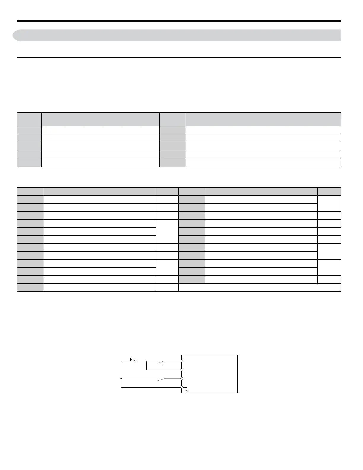
Setting 0: 3-Wire Sequence
When one of the digital inputs is programmed for 3-Wire control, that input becomes a forward/reverse directional input, S1
becomes the Run command input, and S2 becomes the Stop command input.
The drive will start the motor when the Run input S1 is closed for longer than 50 ms. The drive will stop the operation when
the
Stop input S2 is released for a brief moment. Whenever the input programmed for 3-Wire sequence is open, the drive will
be set for forward direction. If the input is closed, the drive is set for reverse direction.
Note: When 3-Wire sequence is selected the Run and Stop command must be input at S1 and S2.
S1
S2
S5
SC
Run Command (Runs when Closed)
DRIVE
Stop Switch
(N.C.)
Run Switch
(N.O.)
Stop Command (Stops when Open)
FWD/REV (Multi-Function Input)
(H1-05 = 0)
Sequence Input Common
Figure 5.14 3-Wire Sequence Wiring Diagram
5.6 H: Terminal Functions
98
YASKAWA ELECTRIC SIEP C710606 31B YASKAWA AC Drive – J1000 Technical Manual
http://nicontrols.com
 Loading...


