3.2 Standard Connection Diagram
Connect
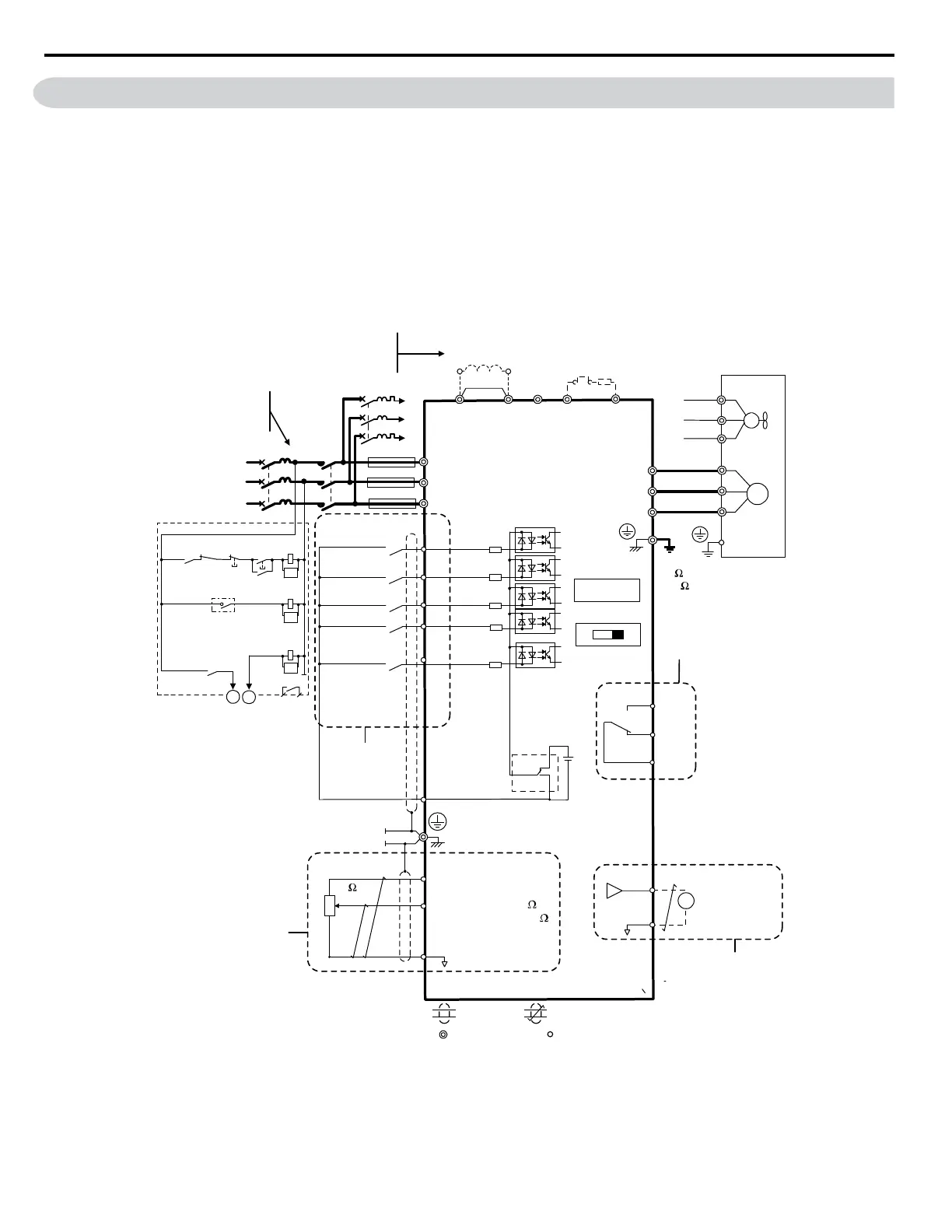
the drive and peripheral devices as shown in Figure 3.1. It is possible to run the drive via the digital operator without
connecting digital I/O wiring. This section does not discuss drive operation; Refer to Start-Up Programming & Operation
on page 55 for instructions on operating the drive.
NOTICE: Inadequate branch short circuit protection could result in damage to the drive. Install adequate branch circuit short circuit protection
per applicable codes. The drive is suitable for circuits capable of delivering not more than 31,000 RMS symmetrical amperes, 240 Vac
maximum (200 V Class) and 480 Vac maximum (400 V Class).
NOTICE: When the wiring distance is greater than 100 meters, pay special attention to the motor insulation voltage or use a drive duty
motor. Failure to comply could lead to motor insulation breakdown.
NOTICE: Do not connect AC control circuit ground to drive enclosure. Improper drive grounding can cause control circuit malfunction.
NOTICE: The minimum load for the multi-function relay output MA-MB-MC is 10 mA.
SA
Motor
Cooling fan
Forward run/stop
Reverse run/stop
External fault
Fault reset
0 to +10 Vdc
(2 mA)
DIP
switch S3
DC link choke
(option)
Digital inputs
(default setting)
Fault
J1000
Shield ground
terminal
Thermal relay
(option)
Braking resistor
(option)
Main circuit
Control circuit
Thermal relay for
motor cooling fan
Fault relay
1 MCCB
MC
2 MCCB
r1
s1
t1
R/L1
S/L2
T/L3
S1
S2
S3
S4
S5
<3>
<1>
<2>
-
B1+1+2 B2
R/L1
S/L2
T/L3
MC
THRX
TRX
MC
TRX
MC MA
U/T1
V/T2
W/T3
24
V
MA
MB
MC
I V
+
24 V 8 mA
M
M
r1
s1
t1
FU
FV
FW
U
V
W
SC
AM
AC
+
-
AM
+V
A1
AC
2 k
Ground
10
or less (400 V class)
100
or less (200 V class)
Setting power supply
+10.5 max. 20 mA
For single phase 200 V
power supply, use
R/L1 and S/L2.
Analog monitor
output
Digital output
250 Vac, 10 mA to 1 A
30 Vdc, 10 mA to 1 A
(default setting)
Main speed
frequency
reference.
Multi-function
programmable
Multi-step
speed 1
main/aux switch
2 MCCB
THRX
OFF
ON
MC
SA
SA
Three phase
power supply
for 200 V /400 V
Jumper
DIP switch S1
Sink
Source
Terminals +1, +2, , B1, and B2
are for connecting options.
Never connect power supply
lines to these terminals.
_
Monitor
output
Option unit
connector
main circuit terminal
shielded line
twisted-pair shielded line
control terminal
<4>
<5>
<6>
<7>
0 to +10 V (20 k )
(0)4 to 20 mA (250 )
Figure 3.1 Drive Standard Connection Diagram (200 V Class Example)
<1> Remove the jumper when installing an optional DC link choke.
<2>
The MC on the input side of the main circuit should open when the thermal relay is triggered.
3.2 Standard Connection Diagram
34
YASKAWA ELECTRIC SIEP C710606 31B YASKAWA AC Drive – J1000 Technical Manual
http://nicontrols.com
 Loading...


