2 mm
D
C
C
B
B
A
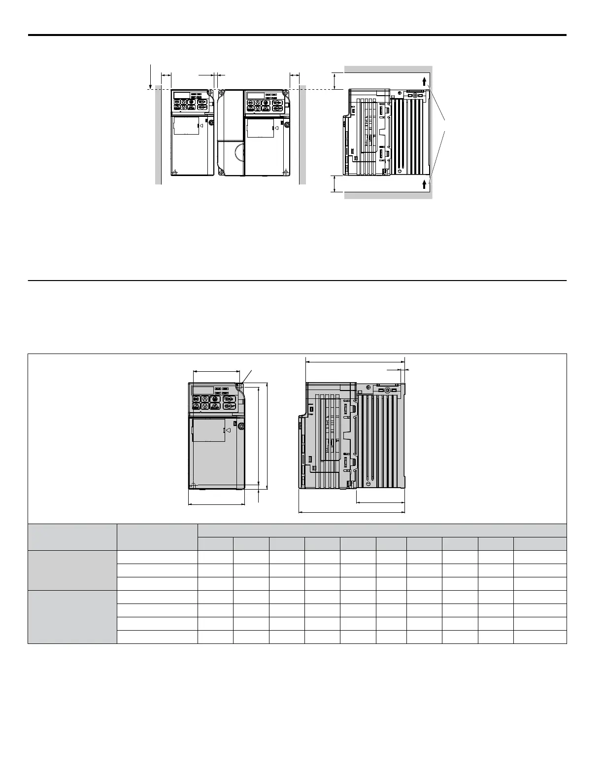
A – Line up the tops of the drives.
B – 30 mm minimum
C – 100 mm minimum
D – Airflow direction
Figure 2.3 Space Between Drives (Side-by-Side Mounting)
Note: When installing drives of different heights in the same enclosure panel, the tops of the drives should line up. Leave space between the top
and bottom of stacked drives for cooling fan replacement if required. Using this method, it is possible to replace the cooling fans later.
u
Exterior and Mounting Dimensions
Refer
to NEMA Type 1 Kit on page 172 for exterior and mounting dimensions for drives using the NEMA Type 1 Kit option.
n
IP20/Open-Chassis Drives
Table 2.2 IP20/Open-Chassis (without an EMC filter)
t1
D1
D
W
H1H2
H
2-M4
W1
D2
Voltage Class
Drive Model
CIMR-Jo
Dimensions (in)
W H D W1 H1 H2 D1 D2 t1 Wt. (lb.)
Single-Phase
200 V Class
BA0001B 2.7 5.0 3.0 2.2 4.6 0.2 0.3 2.7 0.1 1.3
BA0002B 2.7 5.0 3.0 2.2 4.6 0.2 0.3 2.7 0.1 1.3
BA0003B 2.7 5.0 4.6 2.2 4.6 0.2 1.5 4.3 0.2 2.2
Three-Phase
200 V Class
2A0001B 2.7 5.0 3.0 2.2 4.6 0.2 0.3 2.7 0.1 1.3
2A0002B 2.7 5.0 3.0 2.2 4.6 0.2 0.3 2.7 0.1 1.3
2A0004B 2.7 5.0 4.3 2.2 4.6 0.2 1.5 3.9 0.2 2.0
2A0006B 2.7 5.0 5.0 2.2 4.6 0.2 2.3 4.7 0.2 2.4
2.2 Mechanical Installation
28
YASKAWA ELECTRIC SIEP C710606 31B YASKAWA AC Drive – J1000 Technical Manual
http://nicontrols.com

 Loading...


