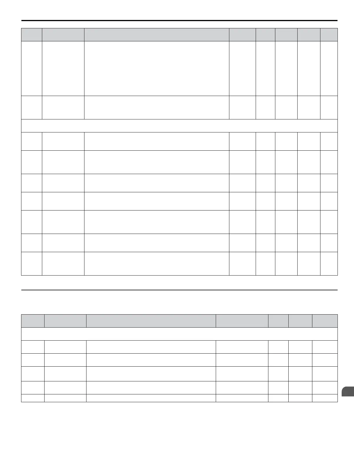
No. Name Description Range Def. Mode
Addr.
Hex
Pg.
o3-01
Copy Function
Selection
Selects the copy function operation.
0: No action
1: READ - All parameters are read from the drive and stored in the
LED operator.
2: COPY - All parameters are copied from the LED operator to the
drive.
3:
VERIFY - Parameter settings in the drive are compared to those in
the LED operator.
Note: When using the copy function, the drive model number (o2-04)
and the software number (U1-26) must match or an error will occur.
0 to 3 0 O 515 123
o3-02
Copy Allowed
Selection
Locks the READ operation to prevent accidental overwriting of the
data stored in the LED operator.
0: READ operation prohibited
1: READ operation allowed
0, 1 0 O 516 124
o4: Maintenance Period
Use o4 parameters to perform maintenance.
o4-01
Accumulated
Operation Time
Setting
Sets the value for the cumulative operation time of the drive in units
of 10 h.
0 to 9999 0 O 50B 124
o4-02
Accumulated
Operation Time
Selection
Determines, how the cumulative operation time (U4-01) is counted.
0: Logs power-on time
1: Logs operation time when the drive output is active (output
operation time).
0, 1 0 O 50C 124
o4-03
Cooling Fan
Operation Time
Setting
Sets the value of the fan operation time in units of 10 h. 0 to 9999 0 O 50E 124
o4-05
Capacitor
Maintenance
Setting
Sets the value of the capacitor maintenance time monitor U4-05. 0 to 150 0% O 51D 124
o4-07
Soft Charge
Bypass Relay
Maintenance
Setting
Sets the value of the Soft Charge Bypass Relay Maintenance monitor
U4-06.
0 to 150 0% O 523 124
o4-09
IGBT
Maintenance
Setting
Sets the value of the IGBT Maintenance monitor U4-07. 0 to 150 0% O 525 125
o4-11
U2 Initialize
Selection
0: U2-oo and U3-oo monitor data are not reset when the drive is
initialized using A1-03.
1: U2-oo and U3-oo monitor data are reset when the drive is
initialized using A1-03.
0, 1 0 O 510 125
<1> Parameter can be changed during run.
u
U: Monitors
Monitor parameters allow the user to view drive status, fault information, and other information about drive operation.
No. Name Description
Analog Output
Level
Unit Mode
Addr.
Hex
U1: Operation Status Monitors
Use U1 monitors to display the operation status of the drive.
U1-01
Frequency
Reference
Monitors the frequency reference 10 V: Max frequency 0.01 Hz O 40
U1-02 Output Frequency
Displays the output frequency. Display units are determined
by o1-03.
10 V: Max frequency 0.01 Hz O 41
U1-03 Output Current Displays the output current.
10 V: Drive rated
current
0.01 A
<1>
O 42
U1-06
Output Voltage
Reference
Displays the output voltage.
10 V: 200 Vrms
(400 Vrms)
0.1 V O 45
U1-07 DC Bus Voltage Displays the DC bus voltage. 10 V: 400 V (800 V) 1 V O 46
B.2 Parameter Table
YASKAWA ELECTRIC SIEP C710606 31B YASKAWA AC Drive – J1000 Technical Manual
201
B
Parameter List
http://nicontrols.com
 Loading...


