Type No. Terminal Name (Function) Function (Signal Level) Default Setting
Main
Frequency
Reference
Input
A1 Frequency reference
Input voltage or input current (Selected by DIP switch S1 and H3-01)
0 to +10 Vdc (20 kΩ),
Resolution: 1/1000
4 to 20 mA (250 Ω) or 0 to 20 mA (250 Ω),
Resolution: 1/500
+V Analog input power supply +10.5 Vdc (max allowable current 20 mA)
AC Frequency reference common 0 Vdc
n
Output Terminals
Table 3.7
Control Circuit Output Terminals
Type No. Terminal Name (Function) Function (Signal Level) Default Setting
Multi-Function Digital
Output
MA N.O. output (fault)
Digital output
30 Vdc, 10 mA to 1 A; 250 Vac, 10 mA to 1 A
Minimum load: 5 Vdc, 10 mA (reference value)
MB N.C. output (fault)
MC Digital output common
Monitor Output
AM Analog monitor output 0 to 10 Vdc (2 mA or less) Resolution: 1/256
AC Monitor common 0 V
u
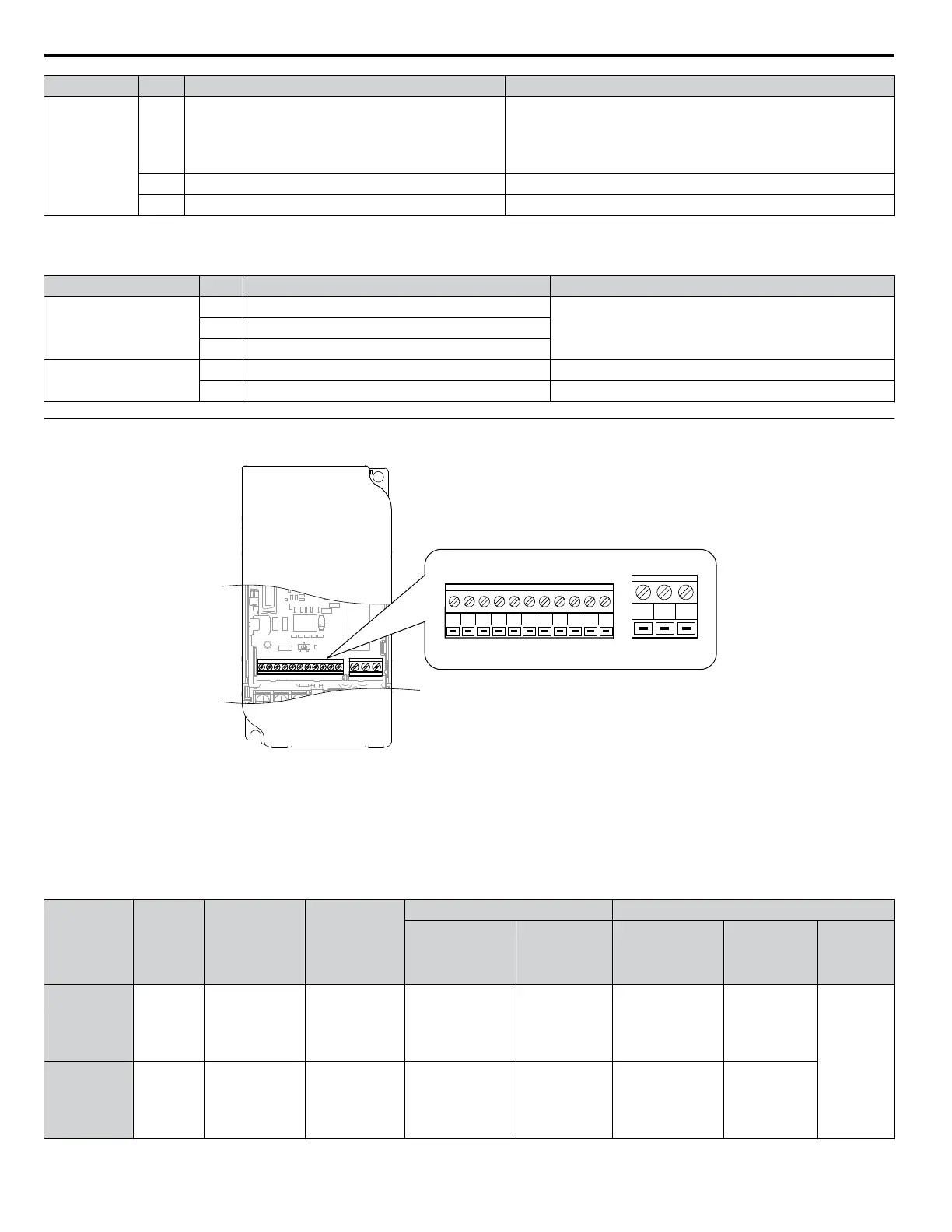
Terminal Configuration
S1 S2 S3 S4 S5 SC A1 +V AC AM AC
MCMBMA
Figure 3.11 Control Circuit Terminal
n
Wire Size and Torque Specifications
Select appropriate wire type and size from Table 3.8. For simpler and more reliable wiring, crimp ferrules to the wire ends.
Refer to Table 3.9 for ferrule terminal types and sizes.
Table 3.8
Wire Size and Torque Specifications (Same for All Models)
Terminal
Screw
Size
Tightening
Torque
N•m
Tightening
Torque
(in-lbs)
Bare Wire Terminal Ferrule-Type Terminal
Applic.
wire size
mm
2
(AWG)
Recomm.
mm
2
(AWG)
Applic.
wire size
mm
2
(AWG)
Recomm.
mm
2
(AWG)
Wire Type
MA, MB, MC M3 0.5 to 0.6 4.4 to 5.3
Stranded: 0.25 to
1.5
(24 to 16)
Single: 0.25 to 1.5
(24 to 16)
0.75 (18)
0.25 to 1.0
(24 to 17)
0.5 (20)
Shielded
line, etc.
S1-S5, SC,
+V, A1, AC,
AM
M2 0.22 to 0.25 1.9 to 2.2
Stranded: 0.25 to
1.0
(24 to 18)
Single: 0.25 to 1.5
(24 to 16)
0.75 (18)
0.25 to 0.5
(24 to 20)
0.5 (20)
3.7 Control Circuit Wiring
44
YASKAWA ELECTRIC SIEP C710606 31B YASKAWA AC Drive – J1000 Technical Manual
http://nicontrols.com
 Loading...


