Setting
Terminal Status
<1>
Detection Method
<2>
Stopping Method
N.O. N.C.
Always
Detected
Detected
during Run
only
Ramp to Stop
(fault)
Coast to Stop
(fault)
Fast-stop
(fault)
Alarm Only
(continue
running)
2E O O O
2F O O O
<1> Determine the terminal status for each fault, i.e., whether the terminal is normally open or normally closed.
<2>
Determine whether detection for each fault should be enabled only during run or always detected.
Setting 40/41: Forward Run/Reverse Run Command for 2-Wire Sequence
Sets the drive for 2-Wire sequence.
When the input set to 40 is closed, the drive operates in the forward direction. When the input set for 41 is closed, the drive
will operate in reverse. Closing both inputs at the same time will result in an external fault.
Note: These functions are assigned to the terminals S1 and S2 when the drive is initialized for 2-Wire sequence.
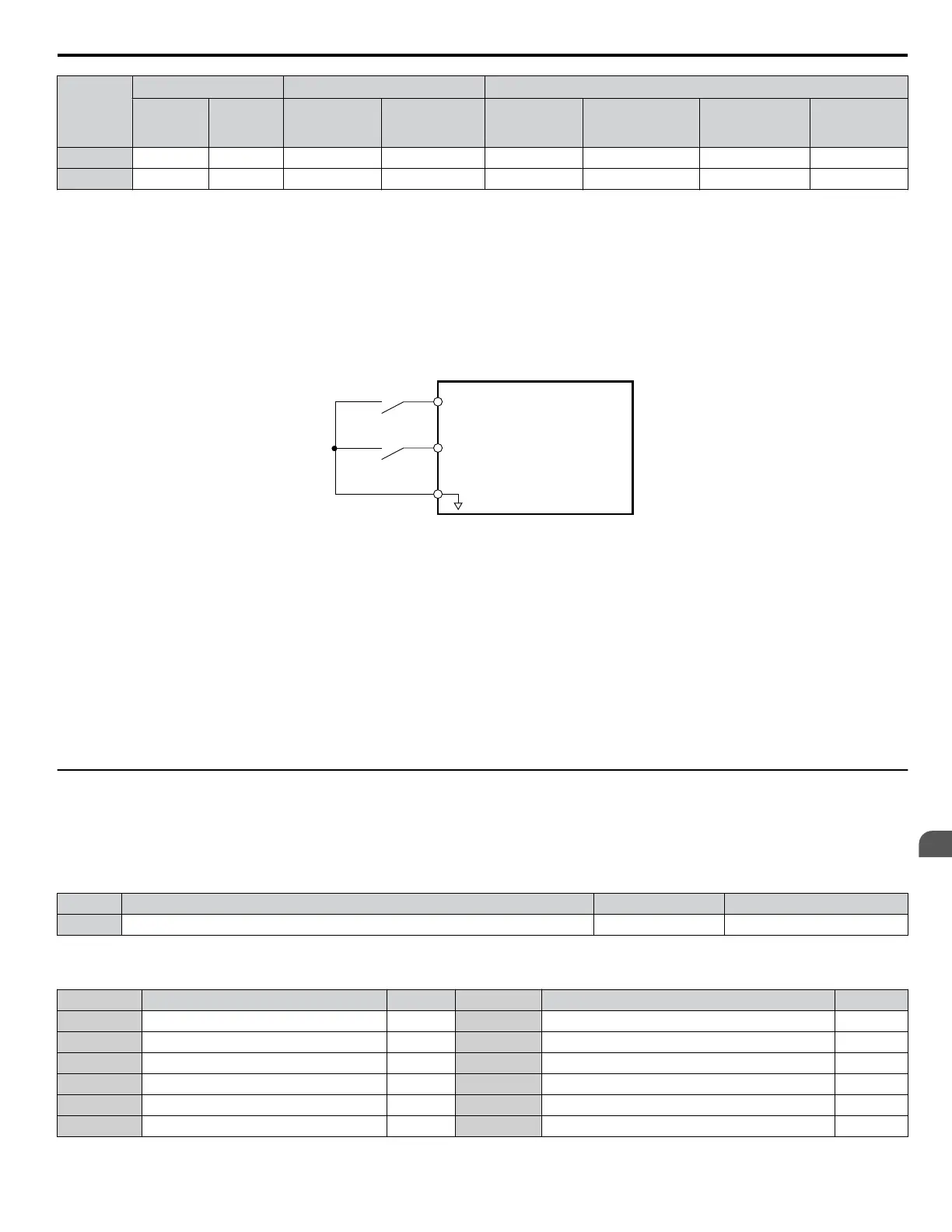
S1
S2
SC
Drive
Forward Run
Reverse Run
Digital Input Common
Figure 5.19 Example Wiring Diagram for 2-Wire Sequence
Setting 61/62: Speed Search 1/2
These
input functions can be used to enable Speed Search. When the Speed Search 1 input (H1-oo = 61) is enabled the drive
will search the motor speed starting from the maximum output frequency. With Speed Search 2 input (H1-oo = 62) enabled
the Speed Search will be performed starting from the frequency reference.
Note: Operator error oPE03 will result if both Speed Search 1 and Speed Search 2 are set to the input terminals at the same time.
Setting 67: Communication Test Mode
If a RS-422/485 communications options is attached to the drive, this function can be used to perform a self-diagnosis of the
communication interface. The drive transmits data and then confirms the communications are received normally. Refer to
Self-Diagnostics on page 232 for details on how to use this function.
u
H2: Multi-Function Output
n
H2-01: Terminal MA/MB/MC Function Selection
The drive has a multi-function output terminal. Set parameter H2-01 between 0 and 13D to assign functions to this terminal.
Default values are listed in the following table.
No. Parameter Name Setting Range Default
H2-01 Terminal MA, MB and MC Function Selection (relay) 0 to 13D E: Fault
Note: If not using an input terminal or if using it in the through-mode, be sure to set that terminal to “F”.
Table 5.16
Multi-Function Output Terminal Settings
Setting Function Page Setting Function Page
0 During Run 104 E Fault 106
1 Zero Speed 104 F Not used/Through Mode 106
2 Speed Agree 104 10 Alarm 107
4 Frequency Detection 1 105 17 Torque Detection 1 (N.C.) 106
5 Frequency Detection 2 105 1A During Reverse Operation 107
6 Drive Ready 106 1E Restart Enabled 107
5.6 H: Terminal Functions
YASKAWA ELECTRIC SIEP C710606 31B YASKAWA AC Drive – J1000 Technical Manual
103
5
Parameter Details
http://nicontrols.com
 Loading...


