No. Parameter Name Setting Range Default
d2-02 Frequency Reference Lower Limit 0.0 to 110.0% 0.0%
Internal frequency
reference
d2-01
Operating
range
Frequency Reference Upper Limit
Set frequency reference
Frequency Reference Lower Limit
d2-02
Figure 5.10 Frequency Reference: Upper and Lower Limits
u
d3: Jump Frequency
n
d3-01, d3-02, d3-04: Jump Frequencies 1, 2, and Jump Frequency Width
In order to avoid continuous operation at a speed that causes resonance in driven machinery, the drive can be programmed
with three separate Jump frequencies that will not allow continued operation within specific frequency ranges. If the speed
reference
falls within a Jump frequency dead band, the drive will clamp the frequency reference just below the dead band and
only accelerate past it when the frequency reference rises above the upper end of the dead band.
Setting parameters d3-01 and d3-02 to 0.0 Hz disables the Jump frequency function.
No. Parameter Name Setting Range Default
d3-01 Jump Frequency 1 0.0 to 400.0 Hz 0.0 Hz
d3-02 Jump Frequency 2 0.0 to 400.0 Hz 0.0 Hz
d3-04 Jump Frequency Width 0.0 to 20.0 Hz 1.0 Hz
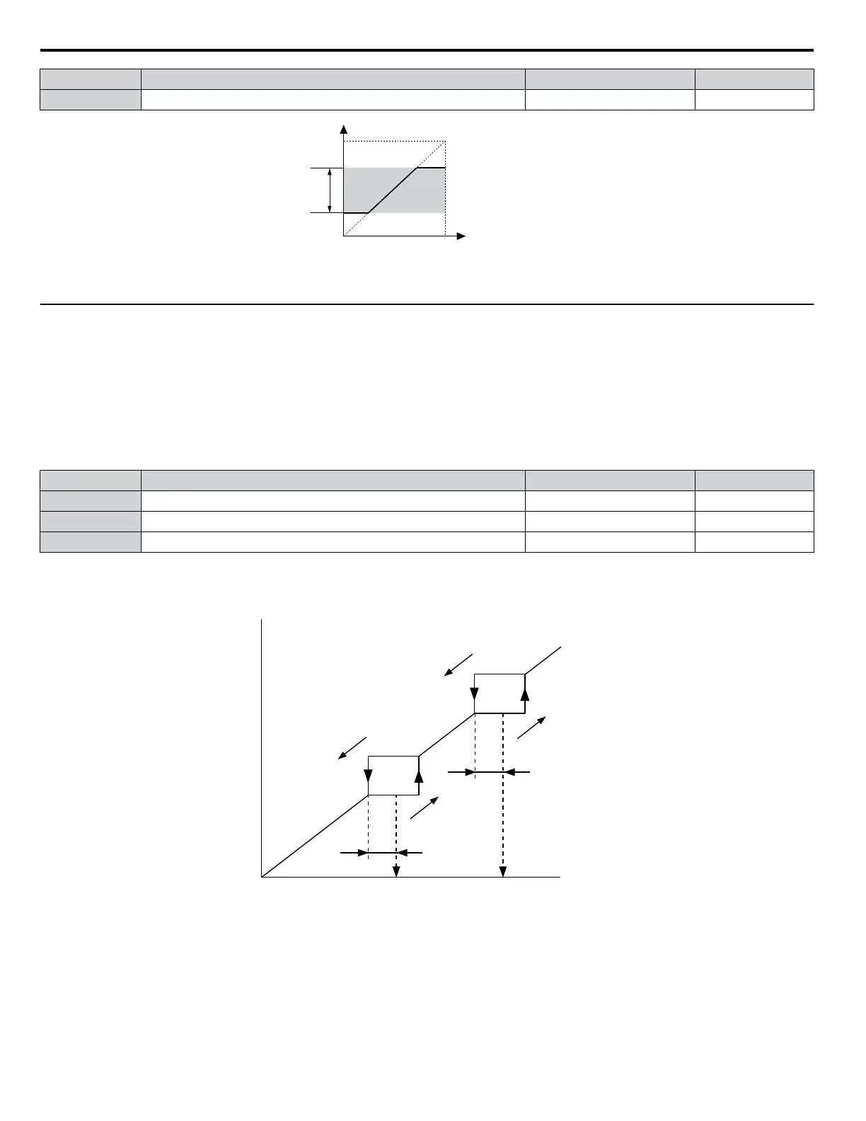
Figure 5.11 shows the relationship between the Jump frequency and the output frequency.
Output
frequency
Frequency
reference
decreases
Frequency
reference
increases
Frequency
reference
Jump Frequency 1
d3-01
Jump Frequency 2
d3-02
Jump
Frequency
Width
d3-04
Jump
Frequency
Width
d3-04
Figure 5.11 Jump Frequency Operation
Note: 1. The drive will use the active accel/decel time to pass through the specified dead band range but will not allow continuous operation in
that range.
2.
When using more than one Jump frequency, make sure that d3-01 ≥ d3-02.
5.4 d: Reference Settings
92
YASKAWA ELECTRIC SIEP C710606 31B YASKAWA AC Drive – J1000 Technical Manual
http://nicontrols.com
 Loading...


