EasyManuals Logo

YASKAWA J1000 Technical Manual

YASKAWA J1000
261 pages
To Next Page IconTo Next Page
To Previous Page IconTo Previous Page
Page #38 background imageLoading...
Page #38 background image
3.4 Terminal Block Configuration
The figures in this section provide illustrations of the main circuit terminal block configurations of the different drive sizes.
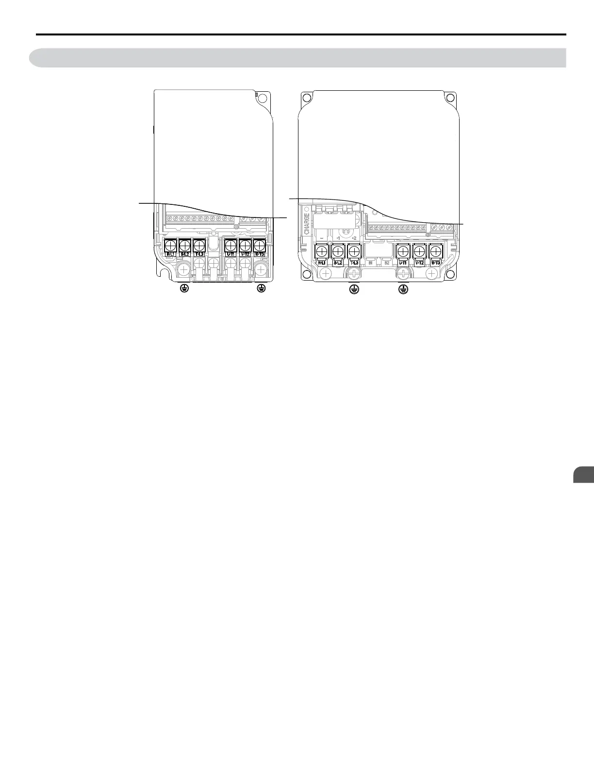
Models:
CIMR-JBA0006, 0010
CIMR-J2A0010, 0012, 0020
CIMR-J4A0001, 0002, 0004, 0005, 0007,
0009, 0011
Models:
CIMR-JBA0001, 0002, 0003
CIMR-J2A0001, 0002, 0004, 0006
Figure 3.5 Main Circuit Terminal Block Configurations
3.4 Terminal Block Configuration
YASKAWA ELECTRIC SIEP C710606 31B YASKAWA AC Drive – J1000 Technical Manual
37
3
Electrical Installation
http://nicontrols.com

Table of Contents

Other manuals for YASKAWA J1000

Questions and Answers:

Question and Answer IconNeed help?

Do you have a question about the YASKAWA J1000 and is the answer not in the manual?

YASKAWA J1000 Specifications

General IconGeneral
SeriesJ1000
Voltage Class200V, 400V
Frequency50/60 Hz
Enclosure RatingIP20
Enclosure TypeOpen type
Voltage200-240V, 380-480V
Control MethodV/f control
Overload Capacity150% for 60 seconds
ProtectionOvercurrent, Overvoltage, Undervoltage, Overheat, Ground Fault, Short Circuit
Protection FeaturesOvercurrent, Overvoltage, Undervoltage, Overheating, Short Circuit
Humidity5-95% (non-condensing)
EnclosureIP20
Input Voltage200-240V, 380-480V

Related product manuals