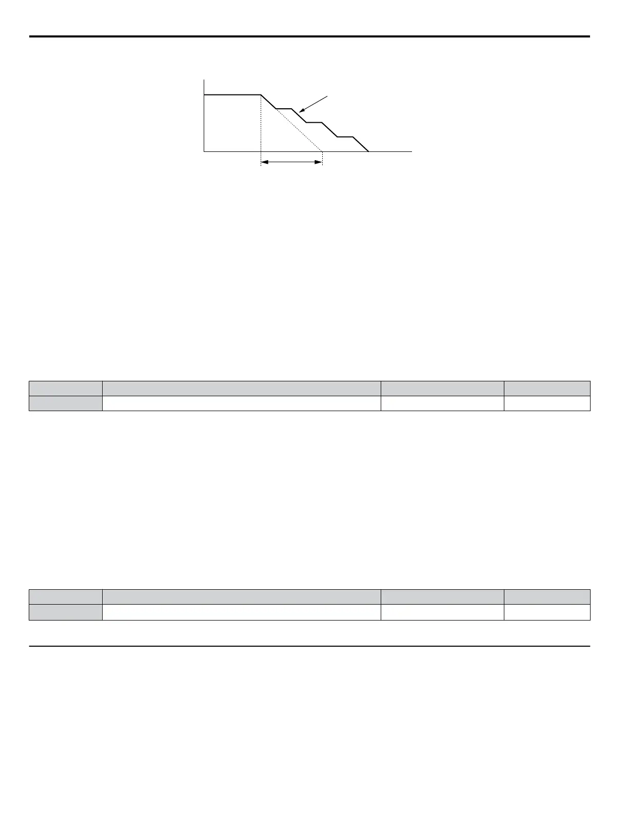
Figure 5.36 illustrates the function of Stall Prevention during deceleration.
Output Frequency
Deceleration characteristics
when Stall Prevention was
triggered during deceleration
Time
specified deceleration time
Figure 5.36 Stall Prevention During Deceleration
Setting 4: Overexcitation Deceleration
Enables overexcitation deceleration. Overexcitation Deceleration (increasing the motor flux) shortens the deceleration time
compared to deceleration with no Stall Prevention (L3-04 = 0). Repetitive or long overexcitation deceleration can result in
motor overheat. In such situations, either shorten the deceleration time setting or use a braking resistor option.
Use parameter n3-13 to fine-tune this function.
Note: Because the allowable flux level for overexcitation varies based on the flux saturation characteristics of the motor, set the proper
overexcitation level by adjusting the excitation gain in parameter n3-13. Motor characteristics and inertia of the machine influence the
deceleration time during overexcitation deceleration.
n
L3-05: Stall Prevention Selection During Run
Stall
Prevention During Run can prevent a motor from stalling by automatically reducing the speed when a transient overload
occurs while the motor is running at constant speed.
This parameter selects the Stall Prevention During Run method.
No. Name Setting Range Default
L3-05 Stall Prevention Selection During Run 0 to 2 1
Note: When output frequency is 6 Hz or less, Stall Prevention During Run is disabled regardless of the setting in L3-05/06.
Setting 0: Disabled
Drive
runs at the set frequency reference. A heavy load may cause the motor to stall and trip the drive with an oC or oL fault.
Setting 1: Decelerate Using C1-02
If the current exceeds the Stall Prevention level set in parameter L3-06, the drive decelerates at Decel Time 1 (C1-02). Once
the current level drops below the value of L3-06 minus 2% for 100 ms it accelerates back to the frequency reference at the
active acceleration time.
Setting 2: Decelerate Using C1-04
Same as setting 1 except the drive decelerates at decel time 2 (C1-04).
n
L3-06: Stall Prevention Level During Run
Sets the current level for Stall Prevention During Run.
No. Name Setting Range Default
L3-06 Stall Prevention Level During Run
30 to 150
<1> <1>
<1> The upper limit and default for this setting is determined by C6-01 and L8-38.
u
L4: Speed Agree
These parameters set up the speed agree and speed detection functions which can be assigned to the multi-function output
terminal MA-MB-MC.
n
L4-01: Speed Agreement Detection Level
Parameter L4-01 sets the detection level for the digital output functions “Speed Agree”, “Frequency Detection 1”, and
“Frequency Detection 2”.
5.7 L: Protection Functions
116
YASKAWA ELECTRIC SIEP C710606 31B YASKAWA AC Drive – J1000 Technical Manual
http://nicontrols.com
 Loading...


