u
E: Motor Parameters
E parameters set V/f characteristics and motor-related data.
No. Name Description Range Def. Mode
Addr.
Hex
Pg.
E1: V/f Pattern Characteristics
Use E1 parameters to set V/f characteristics for the motor.
E1-01
<1>
Input Voltage
Setting
This parameter must be set to the power supply voltage.
WARNING! Drive input voltage (not motor voltage) must be set in
E1-01 for the protective features of the drive to function properly.
Failure to do so may result in equipment damage and/or death or
personal injury.
155 to 255 230 S 300 94
E1-03
V/f Pattern
Selection
F: Custom V/f. E1-04 through E1-10 settings define the V/f pattern. F F O 302 —
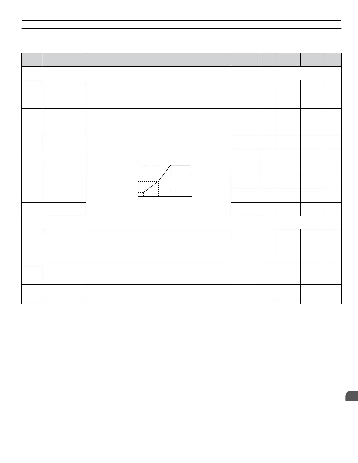
E1-04
Maximum Output
Frequency
To set linear V/f characteristics, set the same values for E1-07 and
E1-09.
In this case, the setting for E1-08 will be disregarded. Ensure
that the four frequencies are set according to these rules:
E1-04 ≥ E1-06> E1-07 ≥ E1-09
E1-05
E1-08
E1-10
E1-09 E1-07 E1-06 E1-04
VACrms Out (V)
Frequency (Hz)
40.0 to
400.0
60 Hz S 303 94
E1-05
<1>
Maximum Output
Voltage
0.0 to 255.0 230 V S 304 94
E1-06 Base Frequency
0.0 to
E1-04
60 Hz O 305 94
E1-07
Middle Output
Frequency
0.0 to
E1-04
3.0 Hz O 306 94
E1-08
<1>
Middle Output
Frequency
Voltage
0.0 to 255.0 18.4 V O 307 94
E1-09
Minimum Output
Frequency
0.0 to
E1-04
1.5 Hz S 308 94
E1-10
<1>
Minimum Output
Frequency
Voltage
0.0 to 255.0 13.8 V O 309 94
E2: Motor Parameters
Use E2 parameters to set motor-related data.
E2-01
Motor Rated
Current
Sets the motor nameplate full load current in amperes.
Note: Set E2-03 (Motor No-Load Current) before making changes
to E2-01. Setting E2-01 < E2-03 will trigger an oPE02 error.
10 to 200%
of drive
rated
current
<2>
S 30E 96
E2-02 Motor Rated Slip Sets the motor rated slip in Hertz.
0.00 to
20.00
<2>
O 30F 96
E2-03
Motor No-Load
Current
Sets the magnetizing current of the motor in amperes.
Note: Set E2-03 (Motor No-Load Current) before making changes
to E2-01. Setting E2-01 < E2-03 will trigger an oPE02 error.
0 to less
than E2-01
<2>
O 310 96
E2-05
Motor
Line-to-Line
Resistance
Sets the phase-to-phase motor resistance in ohms.
0.000 to
65.000
<3>
<2>
O 312 97
<1> Values shown here are for 200 V class drives. Double the value when using a 400 V class drive.
<2>
Default setting value is dependent on parameter o2-04, Drive Model Selection and C6-01, Drive Duty Selection.
<3> Setting range becomes 0.00 to 130.00 for drives 0.2 kW and smaller.
B.2 Parameter Table
YASKAWA ELECTRIC SIEP C710606 31B YASKAWA AC Drive – J1000 Technical Manual
193
B
Parameter List
http://nicontrols.com
 Loading...


