u
Wiring Diagram for Multiple Connections
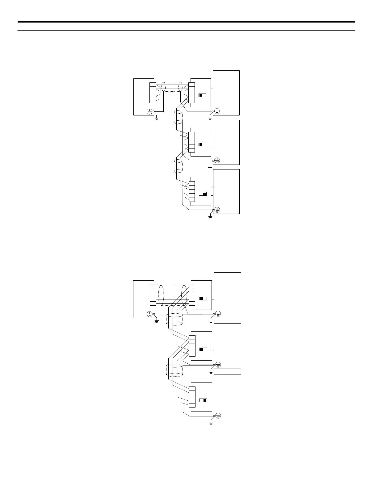
Figure C.3 and Figure C.4 explain the wiring diagrams for multiple connections using MEMOBUS/Modbus communication.
n
RS-485 Interface
SI-485/J
OFF
S2
R–
R+
IG
S–
S+
SI-485/J
OFF
S2
R–
R+
IG
S–
S+
SI-485/J
ON
S2
R–
R+
IG
S–
S+
S+
S–
IG
R+
R–
PLC
Drive
Drive
Drive
Terminating
Register
Terminating
Register
Terminating
Register
Figure C.3 RS-485 Interface
Note: 1. Turn on the DIP switch at the SI-485/J that is located at the end of the network. Turn it off at all other slaves.
2. Set H5-07 to “1” when using the RS-485 interface.
n
RS-422 Interface
S+
S–
IG
R+
R–
PLC
SI-485/J
OFF
S2
R–
R+
IG
S–
S+
SI-485/J
OFF
S2
R–
R+
IG
S–
S+
SI-485/J
ON
S2
R–
R+
IG
S–
S+
Drive
Drive
Drive
Terminating
Register
Terminating
Register
Terminating
Register
Figure C.4 RS-422 Interface
Note: 1. Turn on the DIP switch at the SI-485/J that is located at the end of the network. Turn it off at all other slaves.
2. Set H5-07 to “0” when using the RS-422 interface.
C.4 Connecting to a Network
212
YASKAWA ELECTRIC SIEP C710606 31B YASKAWA AC Drive – J1000 Technical Manual
http://nicontrols.com
 Loading...


