No. Name Description Range Def. Mode
Addr.
Hex
Pg.
b1-14
Phase Order
Selection
Sets the phase order for drive output terminals U/T1, V/T2 and W/
T3.
0 : Standard
1 : Switch phase order
0, 1 0 O 1C3 83
b1-17
Run Command at
Power Up
Determines the operation when a Run command is active at power
up of the drive.
0: Run command not issued, needs to be cycled
1: Run command issued, motor operation start
0, 1 0 O 1C6 83
b2: DC Injection Braking
Use b2 parameters to configure DC Injection Braking operation
b2-02
DC Injection
Braking Current
Sets the DC Injection Braking current as a percentage of the drive
rated current.
0 to 75 50% O 18A 83
b2-03
DC Injection
Braking Time/DC
Excitation Time at
Start
Sets DC Injection Braking time at start. Disabled when set to 0.00
seconds.
0.00 to
10.00
0.00 s O 18B 83
b2-04
DC Injection
Braking Time at
Stop
Sets DC Injection Braking time at stop.
When
b1-03 = 0, this parameter sets the amount of DC Injection time
applied to the motor at the end of the decel ramp. Disabled when set
to 0.00.
0.00 to
10.00
0.50 s O 18C 84
u
C: Tuning
C parameters are used to adjust the acceleration and deceleration times, S-curves, slip and torque compensation functions and
carrier frequency selections.
No. Name Description Range Def. Mode
Addr.
Hex
Pg.
C1: Acceleration and Deceleration Times
Use C1 parameters to configure motor acceleration and deceleration.
C1-01
<1>
Acceleration Time
1
Sets the time to accelerate from 0 to maximum frequency.
0.0 to
6000.0
10.0 s
S 200 85
C1-02
<1>
Deceleration Time
1
Sets the time to decelerate from maximum frequency to 0. S 201 85
C1-03
<1>
Acceleration Time
2
Sets the time to accelerate from 0 to maximum frequency when
Accel/Decel times 2 are selected by a digital input.
O 202 85
C1-04
<1>
Deceleration Time
2
Sets the time to decelerate from maximum frequency to 0 when
Accel/Decel times 2 are selected by a digital input.
O 203 85
C1-09 Fast-Stop Time
Sets the time to decelerate from maximum frequency to 0 for the
multi-function input fast-stop function.
Note:
This parameter is also used by selecting “Fast-Stop” as a Stop
Method when a fault is detected.
O 208 85
C2: S-Curve Characteristics
Use C2 parameters to configure S-curve operation.
C2-01
S-Curve
Characteristic at
Accel Start
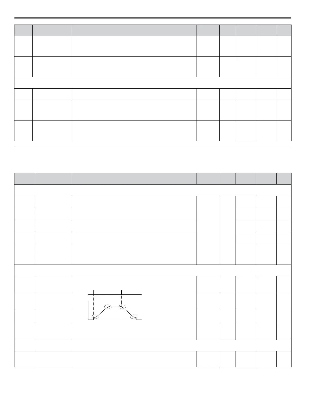
The S-curve can be controlled in the four points shown below.
Run
command
Output
frequency
Time
C2-01
C2-04
C2-02
C2-03
ON
OFF
S-curve is used to further soften the starting and stopping ramp. The
longer the S-curve time, the softer the starting and stopping ramp.
0.00 to
10.00
0.20 s O 20B 86
C2-02
S-Curve
Characteristic at
Accel End
0.00 to
10.00
0.20 s O 20C 86
C2-03
S-Curve
Characteristic at
Decel Start
0.00 to
10.00
0.20 s O 20D 86
C2-04
S-Curve
Characteristic at
Decel End
0.00 to
10.00
0.00 s O 20E 86
C3: Slip Compensation
Use C3 parameters to configure the slip compensation function.
C3-01
<1>
Slip Compensation
Gain
Sets the slip compensation gain. Decides for what amount the output
frequency is boosted in order to compensate the slip.
Note: Adjustment is not normally required.
0.0 to 2.5 0.0 O 20F 86
B.2 Parameter Table
190
YASKAWA ELECTRIC SIEP C710606 31B YASKAWA AC Drive – J1000 Technical Manual
http://nicontrols.com
 Loading...


