No. Name Description Range Def. Mode
Addr.
Hex
Pg.
C3-02
Slip Compensation
Primary Delay Time
Adjusts the slip compensation function delay time.
Decrease the setting when the slip compensation response is too
slow, increase it when the speed is not stable.
0 to 10000
2000
ms
O 210 86
C4: Torque Compensation
Use C4 parameters to configure Torque Compensation function.
C4-01
<1>
Torque
Compensation Gain
Sets the gain for the automatic torque (voltage) boost function and
helps to produce better starting torque.
Increase this setting when using a long motor cable or when the
motor is significantly smaller than the drive capacity.
Decrease
this setting when motor oscillation occurs. Set the value so
that the current at low speed does not exceeds the drive rated current.
0.00 to
2.50
1.00 O 215 87
C6: Carrier Frequency
Use C6 parameters to configure the carrier frequency drive settings.
C6-01
Drive Duty
Selection
Selects the load rating for the drive.
0: Heavy Duty (HD) for constant torque applications.
1: Normal Duty (ND) for variable torque applications.
This setting affects the Rated output current and overload tolerance
of the drive.
0, 1 1 S 223 87
C6-02
Carrier Frequency
Selection
Selects the carrier frequency
1 : 2.0 kHz
2 : 5.0 kHz
3 : 8.0 kHz
4 : 10.0 kHz
5 : 12.5 kHz
6 : 15.0 kHz
7 : Swing PWM
8 to E : No setting possible
F: User defined (determined by C6-03 through C6-05)
1 to F
<2>
S 224 88
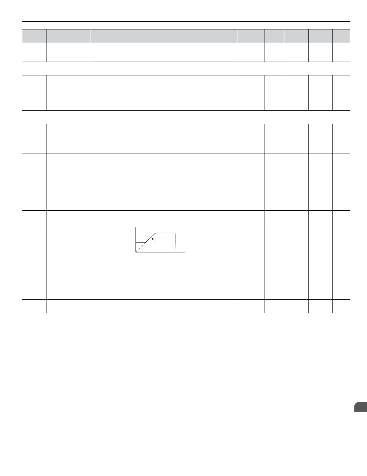
C6-03
Carrier Frequency
Upper Limit
C6-03 and C6-04 set upper and lower limits for the carrier frequency.
Note: Set C6-02 to F before setting C6-03.
carrier frequency
E1-04
max output
frequency
output frequency
× (C6-05) × K
output
frequency
C6-03
C6-04
The coefficient K depends on C6-03:
C6-03 ≥ 10.0 kHz: K = 3
10.0 kHz > C6-03 ≥ 5.0 kHz: K = 2
5.0 kHz > C6-03: K = 1
When C6-05 ≤ 6, C6-04 is disabled (makes the carrier frequency
C6-03 value).
1.0 to 15.0
<3>
O 225 88
C6-04
Carrier Frequency
Lower Limit
1.0 to 15.0
<3>
O 226 88
C6-05
Carrier Frequency
Proportional Gain
Sets the relationship of output frequency to carrier frequency when
C6-02 = F.
00 to 99
<3>
O 227 88
<1> Parameter can be changed during run.
<2>
Default setting value is dependent on parameter o2-04, Drive Model Selection and C6-01, Drive Duty Selection.
<3> Default setting value is dependent on parameter C6-02, Carrier Frequency Selection.
B.2 Parameter Table
YASKAWA ELECTRIC SIEP C710606 31B YASKAWA AC Drive – J1000 Technical Manual
191
B
Parameter List
http://nicontrols.com
 Loading...


