CB
A
D
R/L1
MCCB
S/L2
T/L3
U/T1
V/T2
W/T3
1
2
3
4
5
6
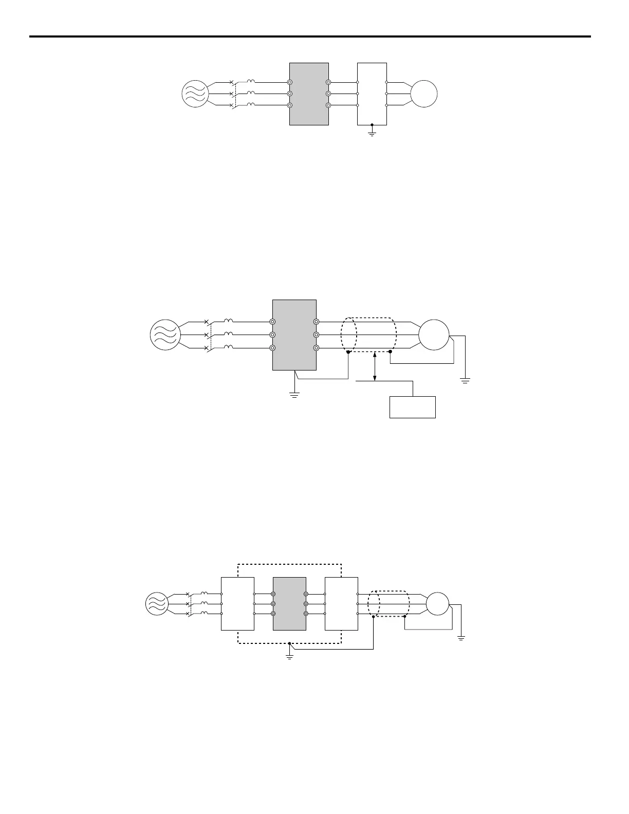
A – Power supply
B – Drive
C – Output-side noise filter
D – Motor
Figure 8.7 Output-Side Noise Filter
• Radiated Noise: Electromagnetic waves radiated from the drive and cables create noise throughout the radio bandwidth
that can affect devices.
• Induced Noise: Noise generated by electromagnetic induction can affect the signal line and may cause the controller to
malfunction.
Preventing Induced Noise
Use a noise filter on the output side or use shielded cables. Lay the cables at least 30 cm away from the signal line to prevent
induced noise.
B
A
C
F
G
D
E
R/L1
MCCB
S/L2
T/L3
U/T1
V/T2
W/T3
A – Power supply
B – Drive
C – Shielded motor cable
D – Motor
E – Separate at least 30 cm
F – Controller
G – Signal line
Figure 8.8 Preventing Induced Noise
Reducing Radiated/Radio Frequency Noise
The drive, input lines, and output lines generate radio frequency noise. Use noise filters on input and output sides and install
the drive in a metal enclosure panel to reduce radio frequency noise.
Note: The cable running between the drive and motor should be as short as possible.
C ED
B
F
A
R/L1
MCCB
S/L2
T/L3
U/T1
V/T2
W/T3
G
A – Metal enclosure
B – Power supply
C – Noise filter
D – Drive
E – Noise filter
F – Shielded motor cable
G – Motor
Figure 8.9 Reducing Radio Frequency Noise
8.4 Installing Peripheral Devices
170
YASKAWA ELECTRIC SIEP C710606 31B YASKAWA AC Drive – J1000 Technical Manual
http://nicontrols.com
 Loading...


