Step Display/Result
4.
Press the
key to stop the motor. The RUN light will flash until the motor comes to
a complete stop.
flashing
off
Setting 1: Control Circuit Terminal
This setting requires that the Run and Stop commands are entered from the digital input terminals. The following sequences
can be used:
•
2-Wire sequence:
Two inputs (FWD/Stop-REV/Stop). Initializing the drive by setting A1-01 = 2220, presets the terminals S1 and S2 to these
functions. This is the default setting of the drive. Refer to Setting 40/41: Forward Run/Reverse Run Command for 2-Wire
Sequence on page 103.
• 3-Wire sequence:
Inputs S1, S2, S5 (Start-Stop-FWD/REV). Initialize the drive by setting A1-01 = 3330 presets the terminals S1, S2 and S5
to these functions. Refer to Setting 0: 3-Wire Sequence on page 98.
Setting 2: MEMOBUS/Modbus Communications
Using this setting, the Run command can be entered via RS-422/485 serial communications using the MEMOBUS/Modbus
protocol and the optional SI-485/J Interface for MEMOBUS/Modbus communication. Refer to Peripheral Devices &
Options on page 163. For details about the MEMOBUS/Modbus protocol, Refer to MEMOBUS/Modbus
Communications on page 207.
n
b1-03: Stopping Method Selection
Select how the drive stops the motor when a Stop command is entered or when the Run command is removed.
No. Parameter Name Setting Range Default
b1-03 Stopping Method Selection 0, 1 0
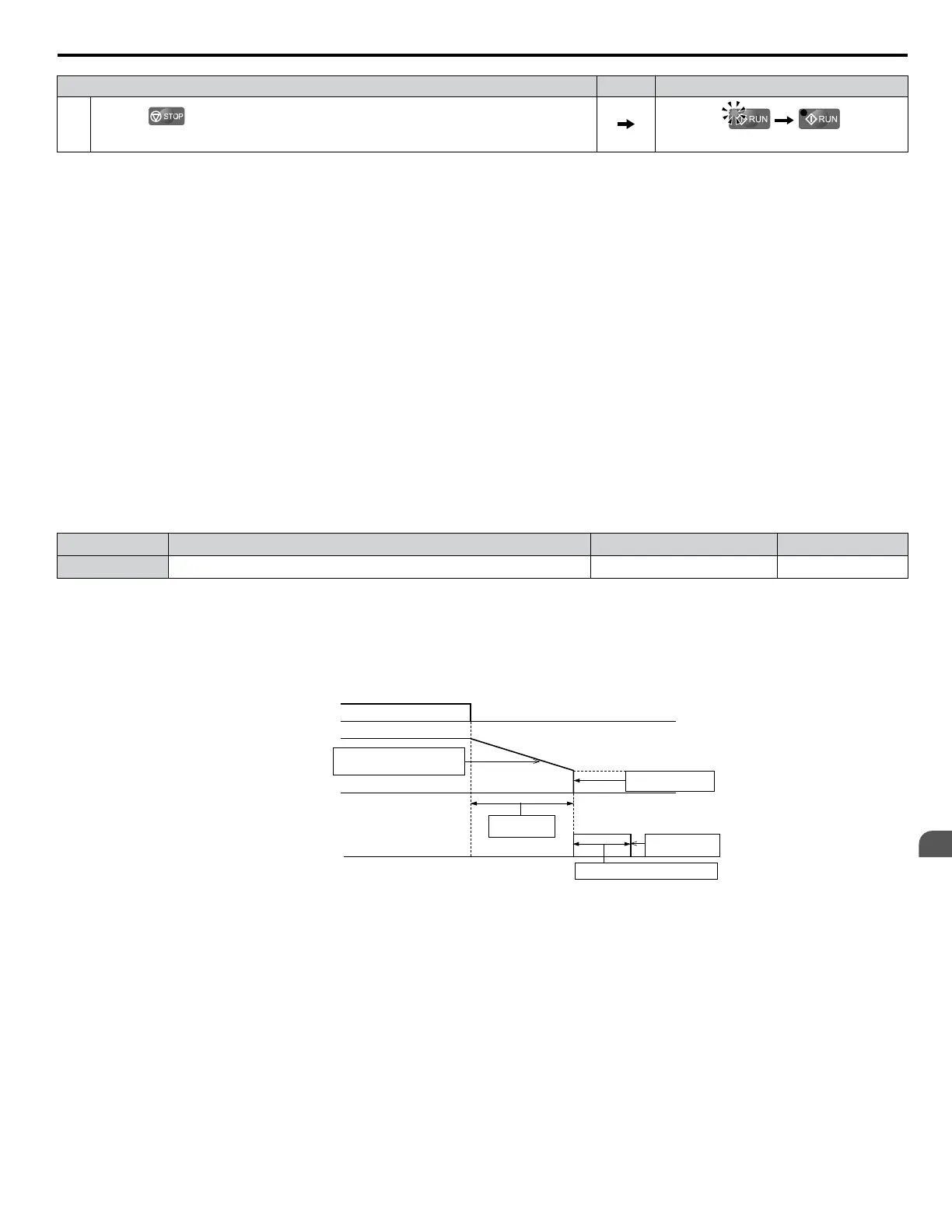
Setting 0: Ramp to Stop
When
a Stop command is issued or the Run command is removed, the drive will decelerate the motor to stop. The deceleration
rate is determined by the active deceleration time. The default deceleration time is set to parameter C1-02.
DC Injection braking can be applied at the end of the ramp in order to completely stop high inertia loads. Refer to b2: DC
Injection Braking on page 83 for details.
Run Command
Decelerates according to the
specified deceleration time
Minimum Output Freq.
(E1-09)
DC Injection
Current (b2-02)
DC Braking
Time at Stop (b2-04)
Decel Time
(C1-02, etc.)
Output Frequency
DC Injection Braking
ON OFF
Figure 5.3 Ramp to Stop
Setting 1: Coast to Stop
When a Stop command is issued or the Run command is removed, the drive will shut off its output and the motor will coast
(uncontrolled
deceleration) to stop where the stopping time is determined by the inertia and the friction in the driven system.
5.2 b: Application
YASKAWA ELECTRIC SIEP C710606 31B YASKAWA AC Drive – J1000 Technical Manual
81
5
Parameter Details
http://nicontrols.com

 Loading...


