4.5 Absolute Encoders
4-43
Note: The output pulses are phase-B advanced if the servomotor is turning forward regardless of the setting in Pn000.0.
Rotational serial data:
Indicates how many turns the motor shaft has made from the reference position, which was the position at
setup.
Initial incremental pulses:
Initial incremental pulses which provide absolute data are the number of pulses required to rotate the motor
shaft from the servomotor origin to the present position.
Just as with normal incremental pulses, these pulses are divided by the dividing circuit inside the SERVO-
PACK and then output.
The initial incremental pulse speed depends on the setting of the encoder output pulses (Pn212). Use the fol-
lowing formula to obtain the initial incremental pulse speed.
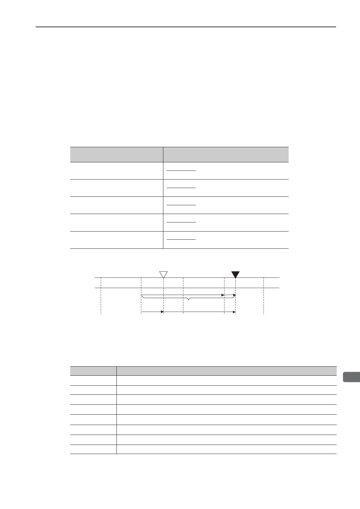
Final absolute data P
M
is calculated by following formula.
P
E
= M × R + P
O
P
S
= M
S
× R + P
S
’
P
M
= P
E
- P
S
Note: The following formula applies in reverse mode. (Pn000.0 = 1)
P
E
= –M × R + P
O
P
S
= M
S
× R + P
S
'
P
M
= P
E
– P
S
Setting of the Encoder Output Pulses
(Pn212)
Formula of the Initial Incremental Pulse Speed
16 to 16384
16386 to 32768
32772 to 65536
65544 to 131072
131088 to 262144
Coordinate
value
Value of M
Reference position
(at setup)
Current position
-1 0 +1 +2 +3
+2+1-1 ±0
P
E
P
M
P
S
P
O
M × R
Signal Meaning
P
E
Current value read by encoder
M Rotational serial data
P
O
Number of initial incremental pulses
P
S
Absolute data read at setup (This is saved and controlled by the host controller.)
M
S
Rotational serial data read at setup
P
S
’
Number of initial incremental pulses read at setup
P
M
Current value required for the user’s system
R Number of pulses per encoder revolution (pulse count after dividing, value of Pn212)

 Loading...


