4 Operation
4.5.5 Absolute Data Reception Sequence
4-42
4.5.5 Absolute Data Reception Sequence
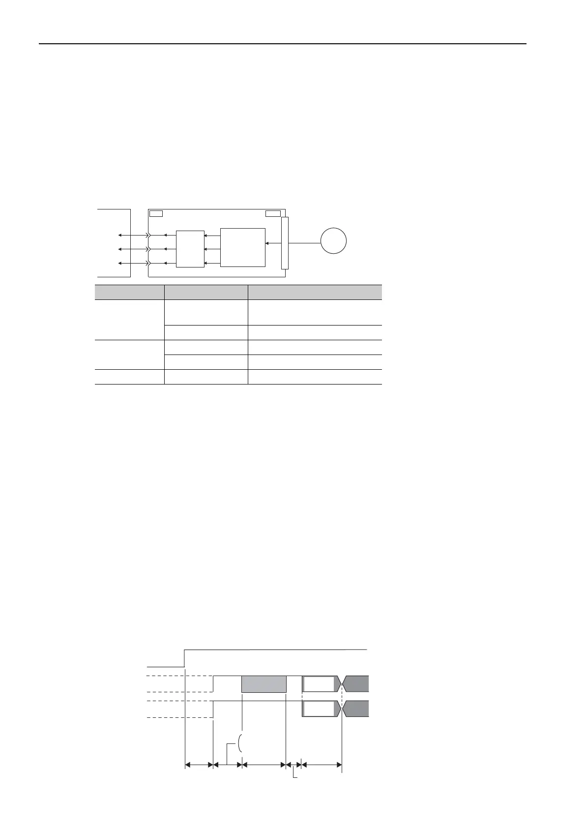
The sequence in which the SERVOPACK receives outputs from the absolute encoder and transmits them to
host controller is shown below.
(1) Outline of Absolute Data
The serial data, pulses, etc., of the absolute encoder that are output from the SERVOPACK are output from the
PAO, PBO, and PCO signals as shown below.
Phase-C Output Specifications
The pulse width of phase C (origin pulse) changes depending on the encoder output pulse (Pn212), becoming
the same width as phase A.
The output timing is one of the following.
• Synchronized with the rising edge of phase A
• Synchronized with the falling edge of phase A
• Synchronized with the rising edge of phase B
• Synchronized with the falling edge of phase B
Note: When host controller receives the data of absolute encoder, do not perform counter reset using the output of PCO
signal.
(2) Absolute Data Reception Sequence
1. Turn ON the Sensor ON command from the host controller.
2. After 100 ms, the system is set to rotational serial data reception standby and the incremental pulse up/
down counter is cleared to zero.
3. Eight characters of rotational serial data is received.
4. The system enters a normal incremental operation state about 400 ms after the last rotational serial data is
received.
Signal Name Status Contents
PAO
At initialization
Rotational serial data
Initial incremental pulses
Normal Operations Incremental pulses
PBO
At initialization Initial incremental pulses
Normal Operations Incremental pulses
PCO Always Origin pulses
ENC
CN1
PAO
PBO
PCO
CN2
Serial
data
Serial data→
pulse conversion
Host
controller
SERVOPACK
Dividing
circuit
(Pn212)
PAO
PBO
Sensor ON
command
Incremental pulses
Incremental pulses
Undefined
Undefined
(Phase A)
(Phase A)
(Phase B)
(Phase B)
Rotational
serial data
400 ms max.
50 ms
1 to 3 ms
Approx. 15 ms
90 ms typ.
60 ms min.
Initial
incremental
pulses
Initial
incremental
pulses

 Loading...


