3 Wiring and Connection
3.3.2 Safety Function Signal (CN8) Names and Functions
3-24
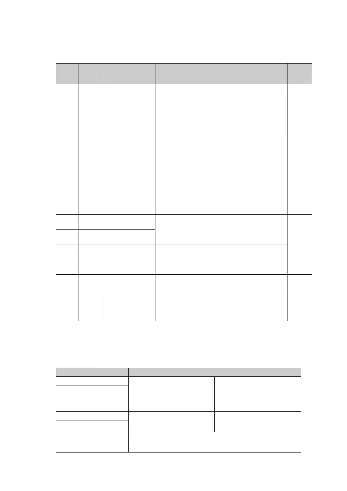
(2) Output Signals
Note: The allocation of the output signals (/SO1 to /SO3) can be changed. For details, refer to 3.4.2 Output Signal Alloca-
tions.
3.3.2 Safety Function Signal (CN8) Names and Functions
The following table shows the terminal layout of safety function signals (CN8).
∗ Do not use pins 1 and 2 because they are connected to the internal circuits.
Signal Pin No. Name Function
Refer-
ence
Section
ALM+
ALM-
31
32
Servo alarm output
signal
Turns OFF when an error is detected. −
/BK+
(/SO1+)
/BK-
(/SO1-)
25
26
Brake interlock signal
Controls the brake. The brake is released when the signal
turns ON.
Allocation can be changed to general-purpose output signals
(/SO1+, /SO1-).
4.2.3
/SO2+
/SO2-
/SO3+
/SO3-
27
28
29
30
General-purpose
output signal
Used for general-purpose output.
Note: Set the parameter to allocate a function.
−
/COIN
/V-CMP
/TGON
/S-RDY
/CLT
/VLT
/WARN
/NEAR
Can be
allocated
Positioning completion
Speed coincidence
detection
Rotation detection
Servo ready
Torque limit
Speed limit detection
Warning
Near
The allocation of an output signal to a pin can be changed in
accordance with the function required.
−
PAO
/PAO
33
34
Phase-A signal
Encoder output pulse signals for two-phase pulse train with
90° phase differential
4.2.5
4.5.5
PBO
/PBO
35
36
Phase-B signal
PCO
/PCO
19
20
Phase-C signal Origin pulse output signal
SG 1 Signal ground
Connects to the 0 V pin on the control circuit of the host con-
troller.
−
FG Shell Frame ground
Connected to frame ground if the shielded wire of the I/O sig-
nal cable is connected to the connector shell.
−
–
2 to 18
23
24
37 to 39
48 to 50
– Do not use these pins. −
Signal Name Pin No. Function
/HWBB1+ 4
Hard wire baseblock input 1
For hard wire baseblock input.
Baseblock (motor current off) when
OFF.
/HWBB1- 3
/HWBB2+ 6
Hard wire baseblock input 2
/HWBB2- 5
EDM1+ 8
Monitored circuit status output 1
ON when the /HWBB1 and the
/HWBB2 signals are input and the
SERVOPACK enters a baseblock state.
EDM1- 7
–
1
*
–
–
2
*
–

 Loading...


