3.5 Examples of Connection to Host Controller
3-31
3.5.2 Sequence Output Circuit
Three types of SERVOPACK output circuit are available.
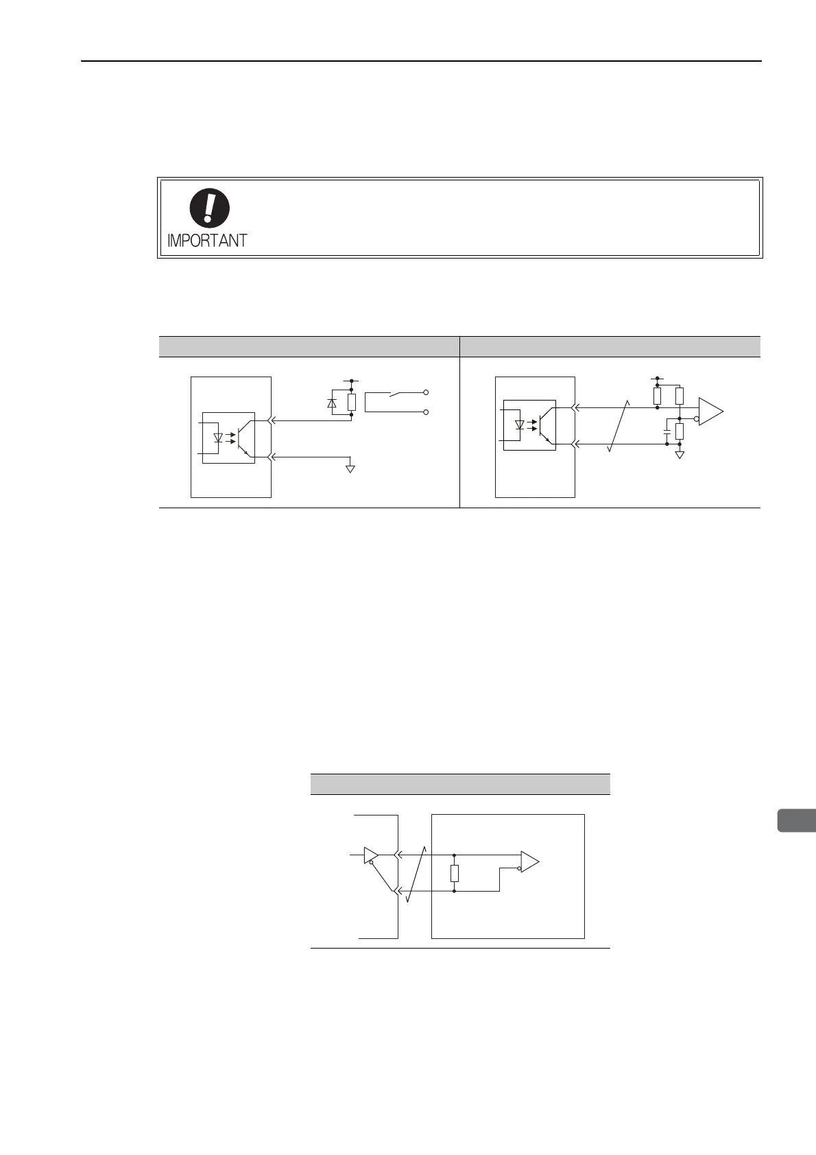
(1) Photocoupler Output Circuit
Photocoupler output circuits are used for servo alarm (ALM), servo ready (/S-RDY), and other sequence out-
put signal circuits. Connect a photocoupler output circuit through a relay or line receiver circuit.
Note: The maximum allowable voltage and the allowable range of current capacity for photocoupler output circuits are as
follows.
• Voltage: 30 VDC
• Current: 5 to 50 mA DC
(2) Line Driver Output Circuit
CN1 connector terminals, 33-34 (phase-A signal), 35-36 (phase-B signal), and 19-20 (phase-C signal) are
explained below.
These terminals output the following signals via the line-driver output circuits.
• Output signals for which encoder serial data is converted as two phases pulses (PAO, /PAO, PBO, /PBO)
• Origin pulse signals (PCO, /PCO)
Connect the line-driver output circuit through a line receiver circuit at the host controller.
Incorrect wiring or incorrect voltage application to the output circuit may cause short-cir-
cuit.
If a short-circuit occurs as a result of any of these causes, the holding brake will not
work. This could damage the machine or cause an accident resulting in death or injury.
Relay Circuit Example Line Receiver Circuit Example
0V
Relay
5 to 24 VDC
SERVOPACK
Line Receiver Circuit Example
SERVOPACK Host Controller
Applicable line receiver:
SN75ALS175 or the
equivalent
220 to
470 Ω

 Loading...


