8.1 System Configuration and Connection Example for SERVOPACK with Fully-closed Loop Control
8-11
8
Fully-closed Loop Control
To output the phase-C pulse when a detection point is passed in reverse, set the following parameter to 1.
Note: When using a serial converter unit, Phase-C pulse is output in forward and reverse direction regardless of the setting
in Pn081.
Parameter Meaning When Enabled Classification
Pn081
n.0
[Factory Setting]
Outputs phase-C pulse only in forward direction.
After restart Setup
n.1
Outputs phase-C pulse in forward and reverse
direction.
Setting of Pn081.0
Do not change the factory setting if the zero point position of the existing equipment must
remain as is.
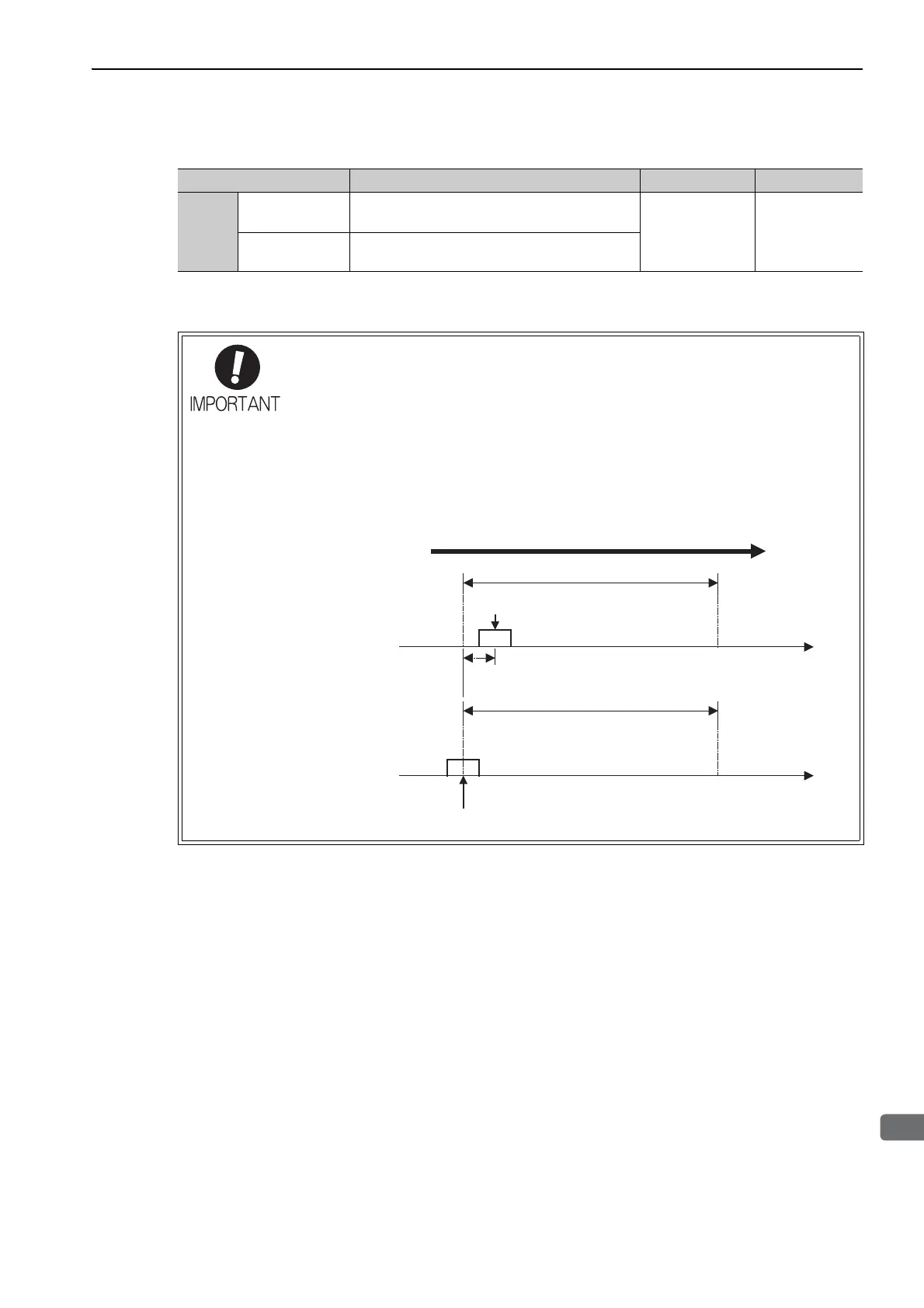
• When Pn081.0 = 1, the width of the phase-C pulse output is narrower than that of the
phase-A pulse in some cases.
• As shown in the following figure, there is a one-eighth scale pitch difference in posi-
tions between the two settings (Pn081.0 = 1 and Pn081.0 = 0) for the phase-C pulse
output, the zero point return command, and the phase-C detection by phase-C latch
function.
1/8scale pitch
Pn081.0 =0
Zero point
Zero point
Moves to forward
1 scale pitch
Pn081.0 =1

 Loading...


