4-15
IM AQ7280-01EN
Optical Pulse Analysis
4
• Marker Features
You can place cursors and markers on the differential trace.
You can display the distance at each cursor position as well as the following values between
markers.
• Loss (dB)
• Distance (km)
• dB/km
• For the operations when marker mode is set to Marker, see “4 Point Markers” on page 4-3.
• For the operations when marker mode is set to Line, see “5 Point Markers” on page 4-6.
• The return loss and splice loss of differential traces cannot be saved.
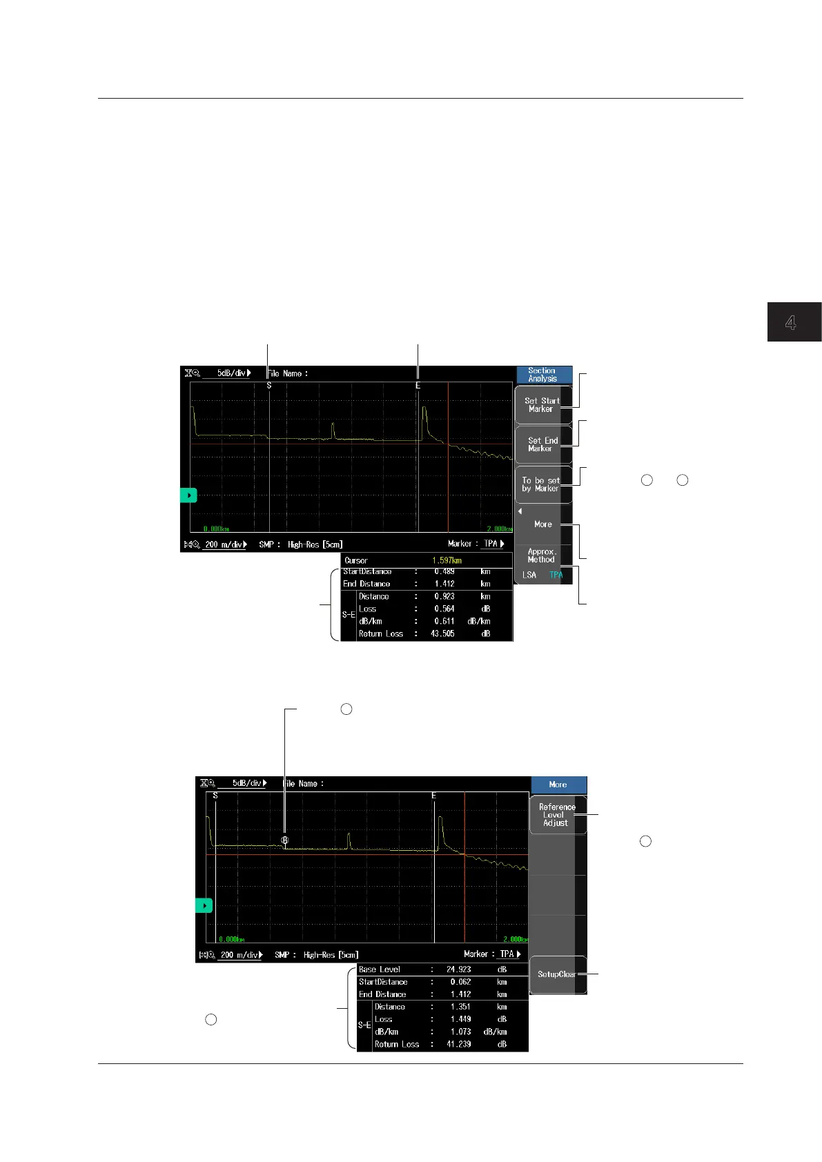
Section Analysis
Press the Section Analysis soft key to display the following screen.
Sets the start point
The start point marker is set
at the cursor position.
Sets the end point
The end point marker is
set at the cursor position.
Specify from markers.
When the and markers
or the n and E markers are
already present, change
these markers to the start
point and end point markers.
1 2
Auxiliary function
See “Adjusting the Reference
Level” below.
Sets the approximation
method (see page 2-3)
Set marker S.
Set marker E.
Section analysis values
Adjusting the Reference Level
Press the More soft key to display the following screen.
This is the reference point for the return loss measurement.
The AQ7280 uses the backscatter level of the reference point
to calculate the return loss. If a reference point is not specified,
the start point is the reference point.
B
Set the reference level
adjustment.
Marker is set at the
cursor position.
B
Clears the settings
The start point, end point,
and reference level
adjustment markers will
be cleared.
Measured value between
and E
B
4.1 Analyzing Waveforms

 Loading...


