3-8
IM AQ7280-01EN
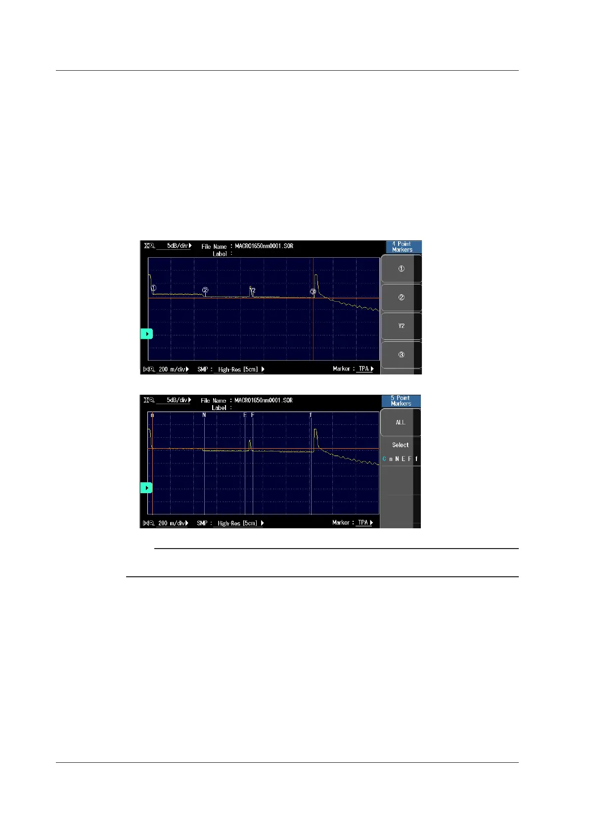
Marker Mode
• Marker
Move the cursor to the location that you want to measure, and set a marker. When you are
measuring return loss and splice loss, they are calculated automatically when you set all the
markers that are necessary for the measurement method that you are using.
• Line
After you select the line marker that you want to operate from a set of multiple line markers,
move the selected line marker directly. The value of the line marker’s section is calculated, and
the return loss and splice loss are measured. Each value is calculated in real time as you move
the line marker.
Note
Line is often used outside of Japan. Marker is often used within Japan. It is used on existing YOKOGAWA
models.
Backscatter Level Base
Select the reference pulse width for detecting backscatter. The selectable range of backscatter
levels in the analysis conditions vary depending on the reference value. For details on backscatter,
see page 2-11.
1µs: The range is ‒64.99 to ‒10.00.
1 ns: The range is –94.99 to ‒40.00.
3.2 Configuring the Waveform Display

 Loading...


