13185L-002 Rev. A 1/24/06 110XiIIIPlus Maintenance Manual Page 4-119
Maintenance Section 4
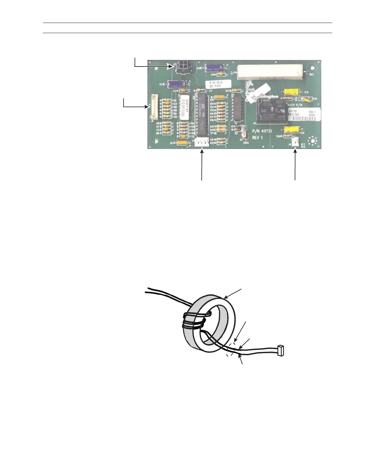
Figure 4-80. Cutter Option Circuit Board
4. Route the cutter motor leads between the two right-hand standoffs and out under the
bottom of the circuit board.
5. Position the cutter circuit board over all four standoffs.
6. Install screw (1) through the lower right-hand circuit board mounting hole. Do not
tighten at this time.
7. Install the three remaining mounting screws (1) and tighten all four screws.
8. Refer to Figure 4-81. Wind the motor leads around the ferrite core.
Figure 4-81. Cutter Motor Leads
9. Pass the cutter board power cable along the bottom of the printer frame toward the
main logic board.
10. Plug the motor leads into the cutter motor connector J4 on the cutter circuit board
with the black lead to the left. To minimize interference between components,
wedge the top of the ferrite core under the cutter board relay.
J4 to Stepper
Motor
J3 to Cutter
Optical Sensor
J1 to Main
Logic Board
J2 to DC
Power Supply
Ferrite Core
Cutter Motor
Leads
Red
Black
 Loading...