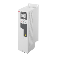
Input power connection (L1, L2, L3),
motor connection (T1/U, T2/V, T3/W)
and brake connection (R-, R+)
11
PE connection (power line)12
Grounding connection (motor)13
Additional grounding connection14
Cable entry15
Main cooling fan16
Cable tie mounts for /I/O cables17
Auxiliary cooling fan. For
IP55/UL Type 12 drives only.
18
Auxiliary cooling fan connector19
Place for storing the removed EMC
screw
20
Place for storing the removed VAR
screw
21
Mounting points (4 pieces)1
Cover2
Cover screw3
Control panel4
Control panel connection5
Cold configuration connection for CCA-
01
6
Power OK and Fault LEDs. See section
LEDs (page 262).
7
I/O connections. See External control
connection terminals, frames
R1…R5 (page 49).
8
Varistor grounding screw (VAR). For
disconnecting, see page 135 (IEC) or
page 180 (North America).
9
EMC filter grounding screw (EMC (DC)).
For disconnecting, see page 135 (IEC) or
page 180 (North America).
10
40 Operation principle and hardware description

 Loading...