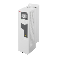
Grounding hole4Analog output scale switch (2)2
Diagnostic LED6Control unit SLOT 2 interface5
-Grounding hole7
■
Mechanical installation
Necessary tools
• Screwdriver and a set of suitable bits.
Unpacking and examining the delivery
1. Open the option package. Make sure that the package contains:
• the option module
• a mounting screw.
2. Make sure that there are no signs of damage.
Installing the module
See section Installing option modules (page 164).
■
Electrical installation
WARNING!
Obey the safety instructions of the drive. If you ignore them, injury or
death, or damage to the equipment can occur.
Stop the drive and do the steps in section Electrical safety precautions (page 24)
before you start the work.
Necessary tools
• Screwdriver and a set of suitable bits.
Wiring
Connect the external control cables to the applicable module terminals. Ground
the outer shield of the control cables 360° under the grounding clamp on the
grounding shelf and the pair cable shield to the SCR terminal of CBAI-01.
Connection diagram:
Optional I/O extension and adapter modules 439

 Loading...